I’m assuming your 0V wires are black?
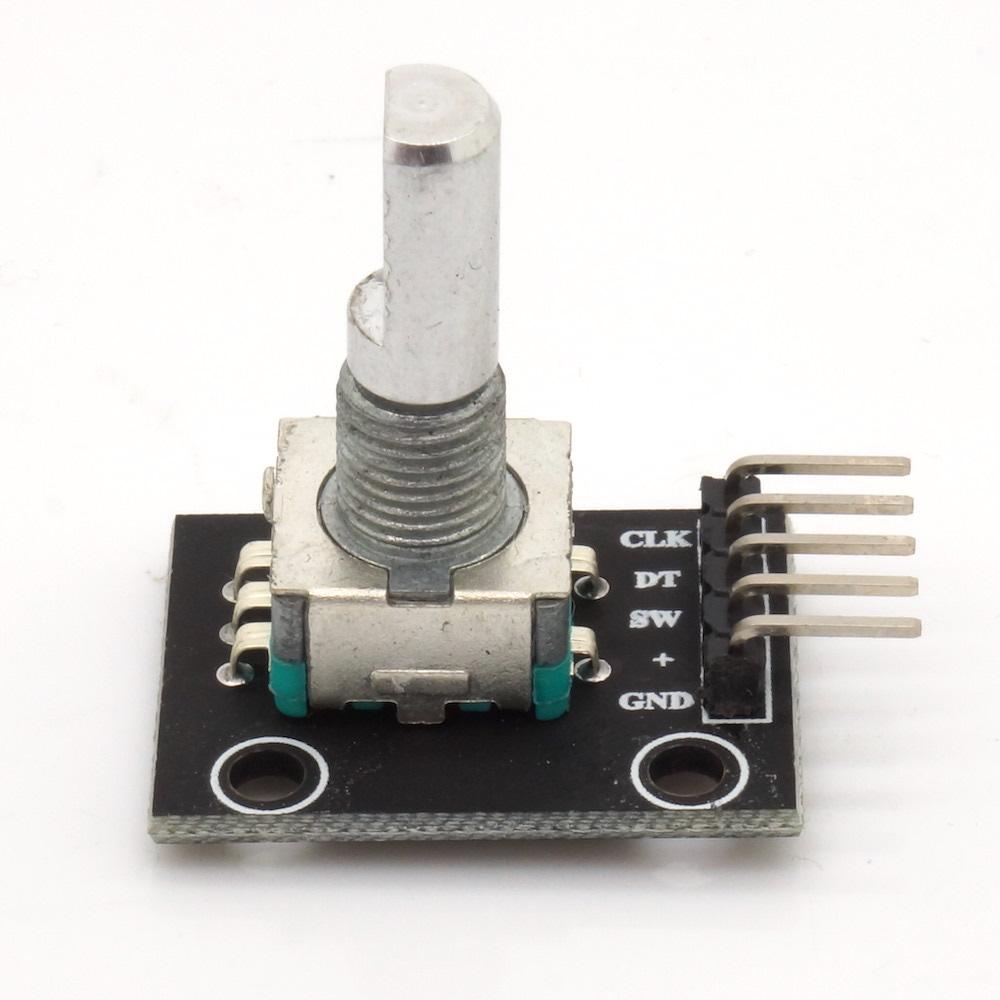
Which is your switch pin on the encoder?
And which colours are encoder A & B?
I’m assuming your 0V wires are black?
Which is your switch pin on the encoder?
And which colours are encoder A & B?
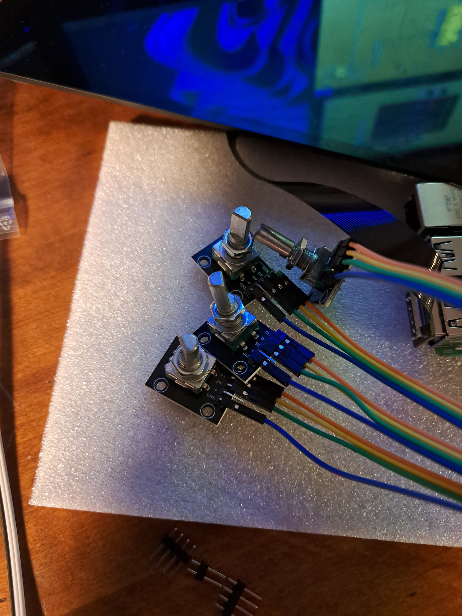
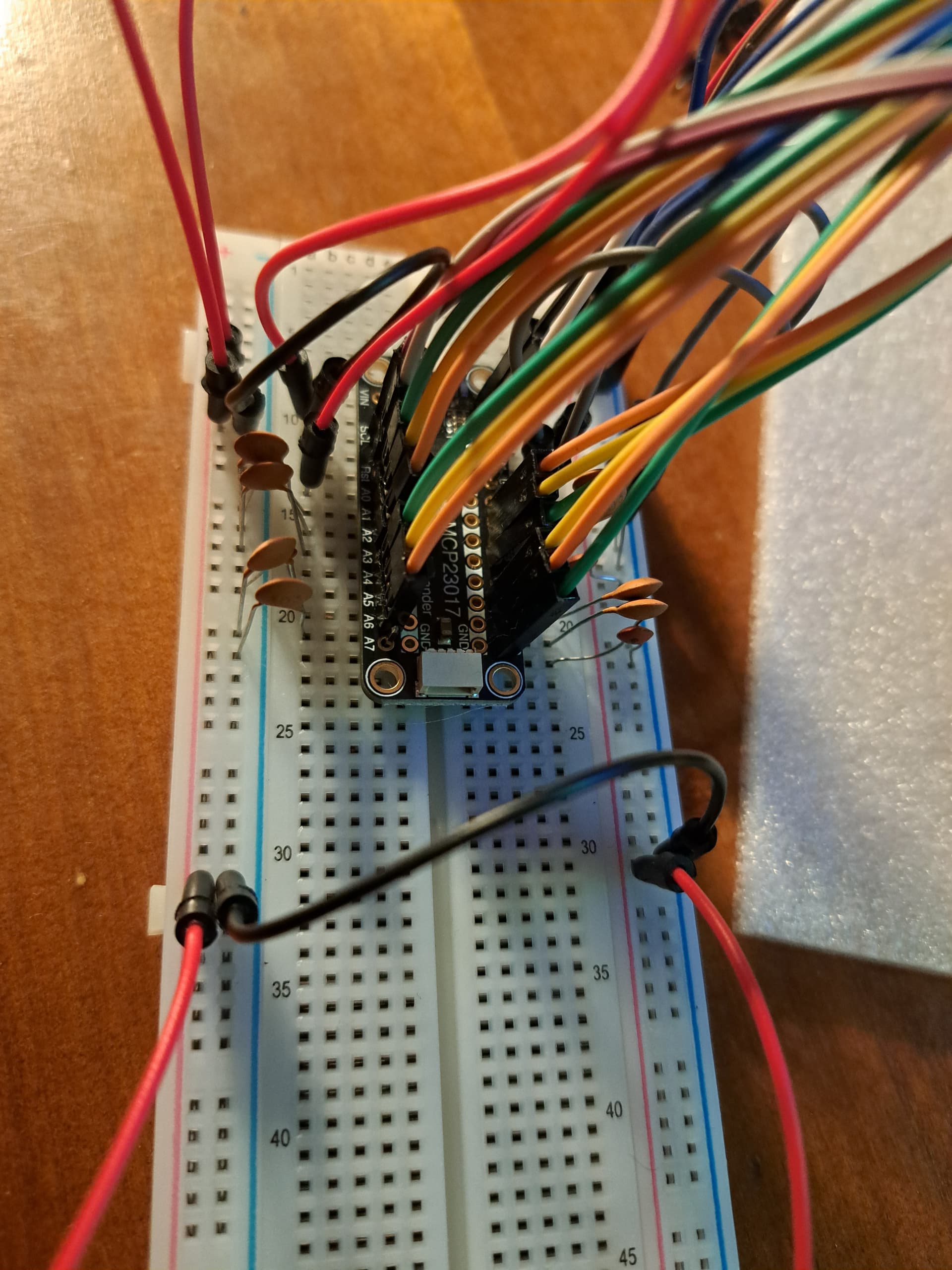
Yes, Red is +, Black is GND, others are more or less by mood, but I thought I would go CLK - DT - SW (green-orange-yellow) while thinking this is only relevant when I enter the webconf stage. (I actually don’t know which of CLK and DT is increment/decrement, but that doesn’t haunt me so much.
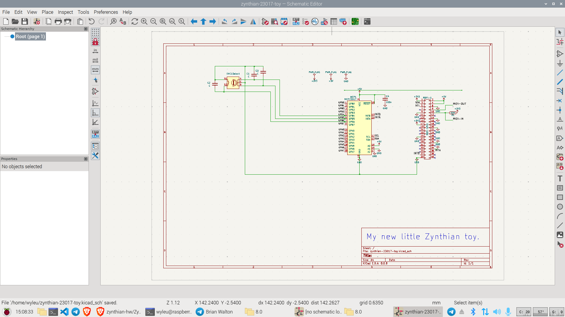
Modifying the Drawing and combining with elements of the original schematic complete with suspect addressing.
Maybe I’ll also do so, because that is what Hifiberry states:
Do not use more than a few mA from the 3.3V line. If your circuit requires 3.3V, use the 5V power rail of the Raspberry Pi with an additional voltage regulator.
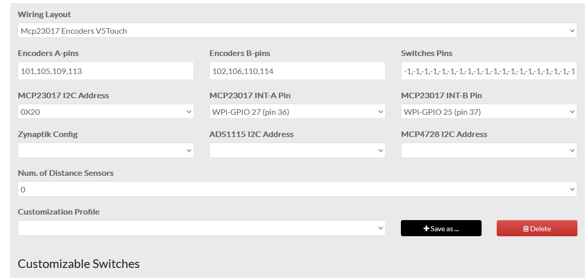
Don’t worry about this… just reverse the pin numbers on WebConf and you’re good to go.
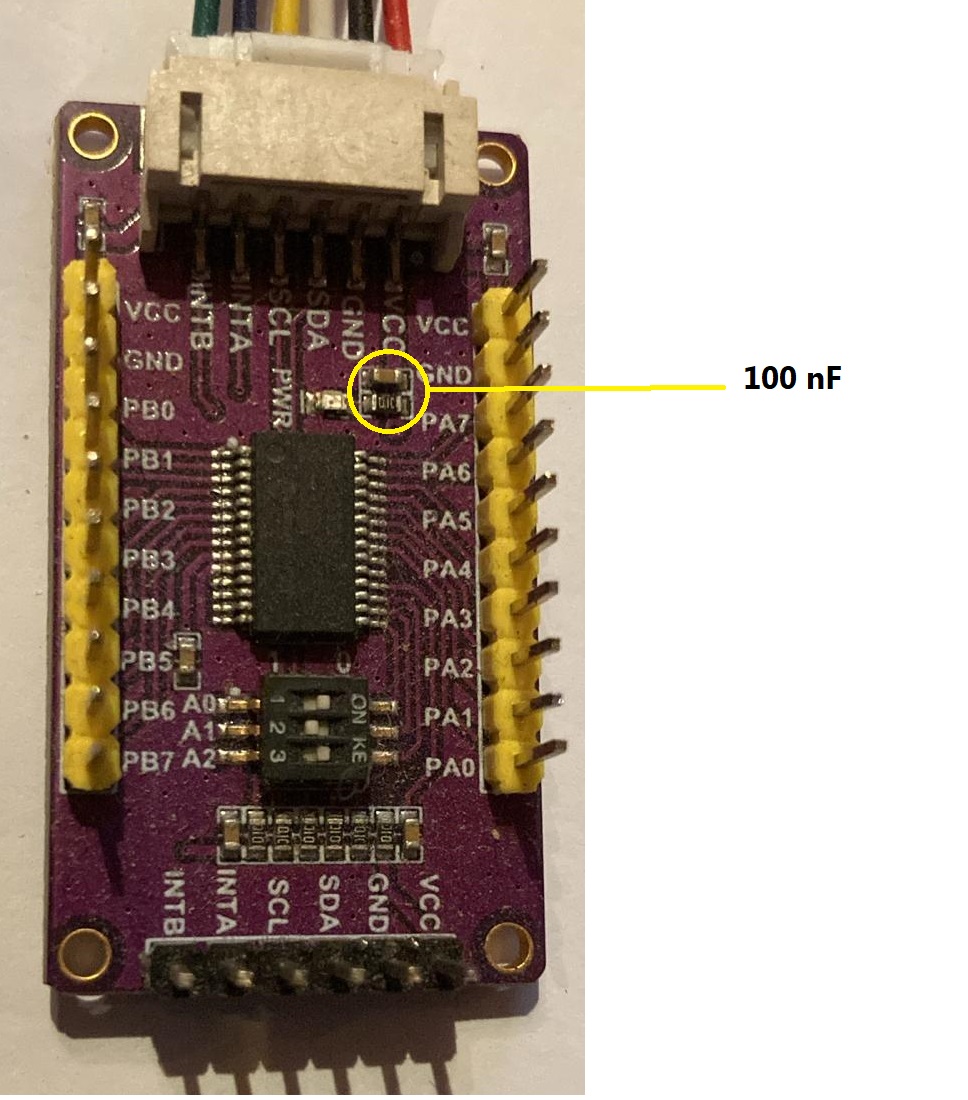
I ordered the MCP…and I found a 100nF capacitor among my things… tantalum… it was stuff to build Radios…
P.S.
I checked in a MCP that I destroyed. The 100nF capacitor is already on board between VCC and GND…
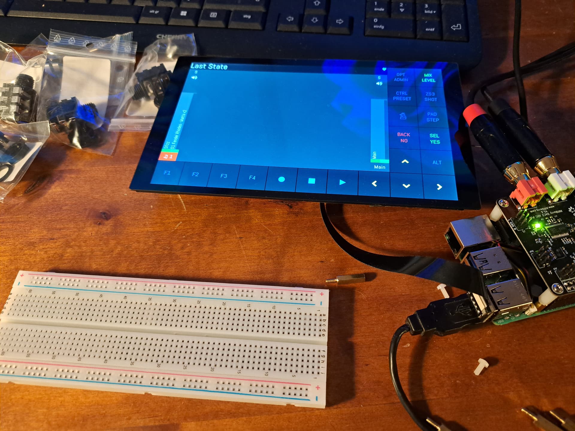
Yeaaaaah! ![]()
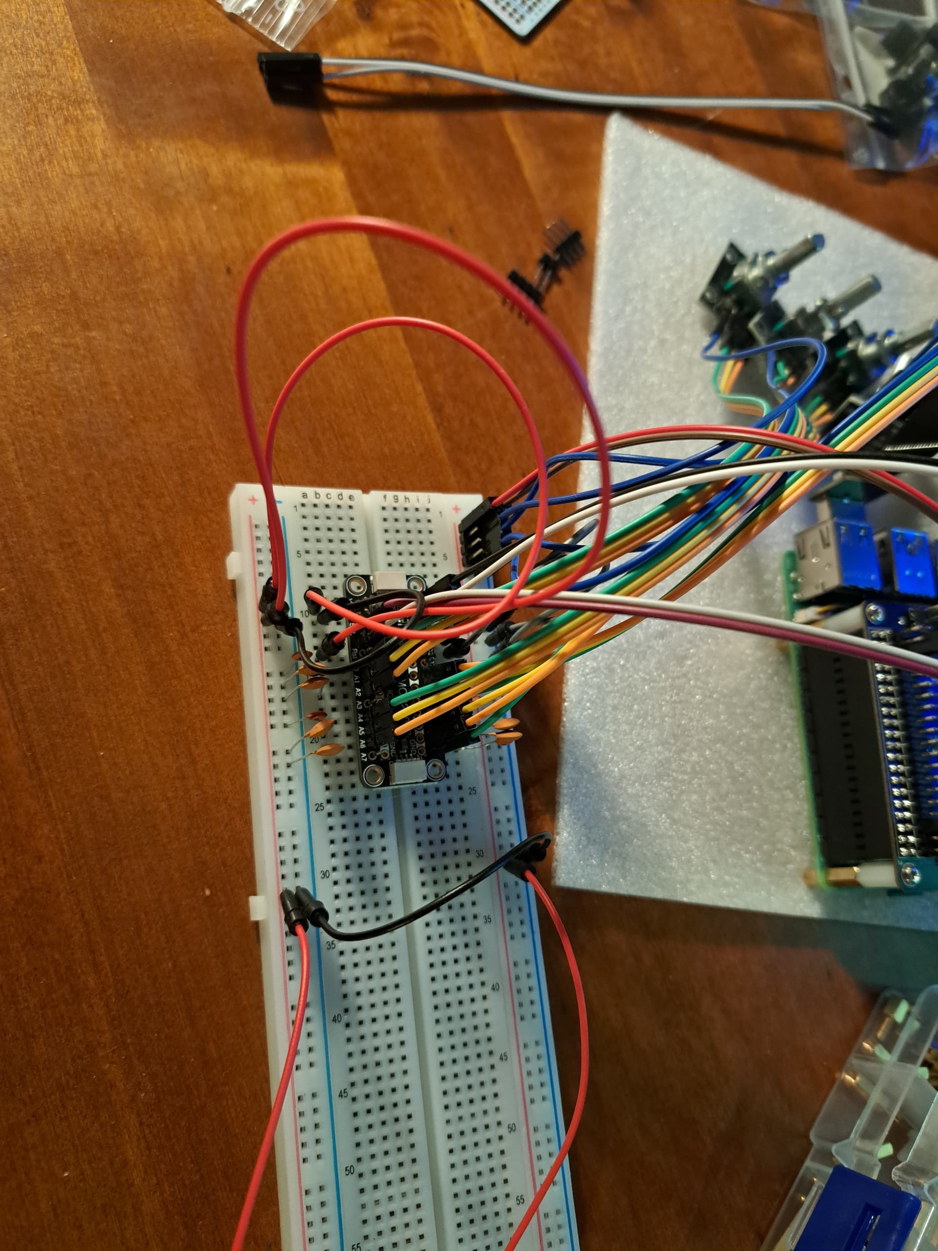
How are you connecting from the Pi Pins on the audio card to the breadboard?
And for the construction where are you locating the Pi and the breadboard in relation to each other?
I read in the Hifiberry forum the dsp header is a copy. So I hope: The same way I would connect to the Pi.
The Pi will go to the left back side of my cigar box (usb to left, hdmi to back). The breadbard will go to the right front side, I heard I should keep the electronics close to the encoders.
It is. I’ve got one here in the cajon.
A good habit is to double check the wiring before turning it on and then… GO!!!
Don’t know.
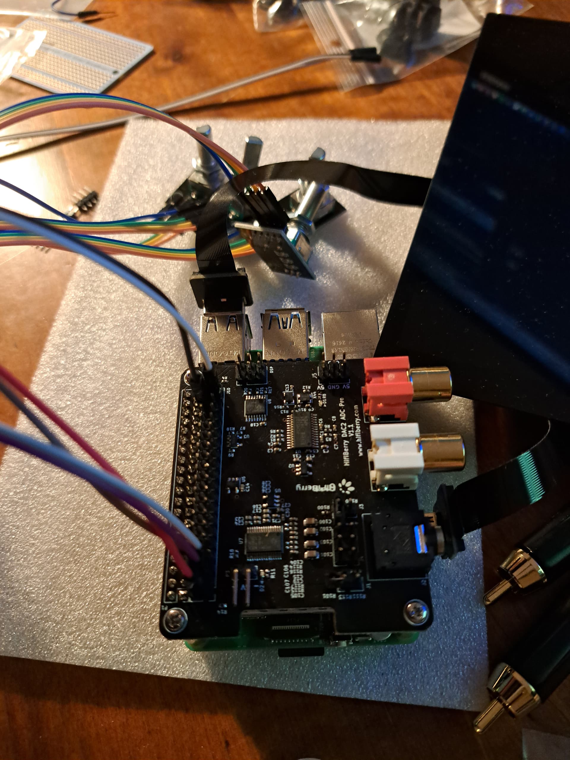
Mine looks like this.
You should try with a multimeter. Anyway, you’ll think about that later… now turn it on because I want to know live how it goes!!
Have you fixed the pins on WebConf?
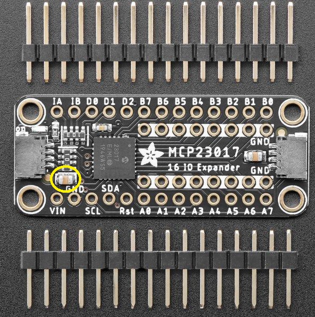
In my opinion your board already has the capacitor… the one highlighted in yellow.
Check the power supllies. And if the pi boots and nothing gets hot. You can progress.
It boots, it makes sound. But no encoder move.
What confuses me is that physical pins 36 and 37 should be WiringPi Numbers 27 and 26?
(venv) root@zynthian:~# systemd stop zynthian
(venv) root@zynthian:~# i2cdetect -y 1
     0  1  2  3  4  5  6  7  8  9  a  b  c  d  e  f
00:                         -- -- -- -- -- -- -- --
10: -- -- -- -- -- -- -- -- -- -- -- -- -- -- -- --
20: -- -- -- -- -- -- -- -- -- -- -- -- -- -- -- --
30: -- -- -- -- -- -- -- -- -- -- -- -- -- -- -- --
40: -- -- -- -- -- -- -- -- -- -- UU -- -- UU -- --
50: -- -- -- -- -- -- -- -- -- -- -- -- -- -- -- --
60: -- -- -- -- -- -- -- -- -- -- -- -- -- -- -- --
70: -- -- -- -- -- -- -- --
Little green light on on the mcp board.
Tomorrow I’ll have some time to evaluate further
Have you got pull up resistors …?
From what I see in the link this would be a resistor each between V+ and SCL, SDA? No, at least I didn’tdo that intentionally.
I read somewhere here that something related had to be solved by connecting encoders V+
Guys, I have never added anything to those MCP boards… it’s all onboard… I would check the board’s datasheet. The capacitors on the encoders are probably enough, but those can be added later… I would try without anything and then, if necessary, once it’s working, I would solve the problems one at a time. So much stuff, so many problems.
It’s a component of the i2c specification, and it can be easily checked with a multimeter power everything off and check the resistance between the two i2c pins and the +V connection on the breakout board. if you see a resistance of 15.k ( can’t remember exactly the recommended values) Then they are installed. There could well be a way of disconnecting them on your board if they are installed somewhere else on the bus.
The fat that i2c has reported to “somethings” on the bus it probably means conversations are good to go, but it’s probably a good idea to check the bus for a hardware requirement mentioned in the specification for the Bus.
To work out what i2cdetect is telling us you can type
man i2cdetect
From using the spacebar to move throu the copious information, you can read…
INTERPRETING THE OUTPUT
       Each  cell  in  the output table will contain one of the following sym-
       bols:

       o "--". The address was probed but no chip answered.

       o "UU". Probing was skipped, because this address is currently  in  use
         by  a driver. This strongly suggests that there is a chip at this ad-
         dress.

       o An address number in hexadecimal, e.g. "2d" or "4e". A chip was found
         at this address.

OPTIONS
       -y     Disable  interactive mode. By default, i2cdetect will wait for a
              confirmation from the user before messing with the I2C bus. When
              this  flag is used, it will perform the operation directly. This
              is mainly meant to be used in scripts.

       -a     Force scanning of non-regular addresses. Not recommended.