It does show almost 10k on each.
Shut up wyleu. . …
The Pi includes pull ups. Presumbly implemented via software which is possibly why you get a 10k ish sort of reading?
Either way they are there so no need to worry about that one.
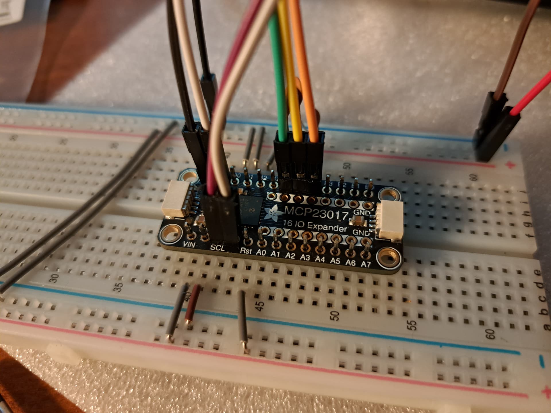
How have you got the Address pins wired?
Try moving it and see if i2cdetect -y 1 helps work out what we actually have in addressing terms.
I wired all to GND. Can I change them “on the fly” or should I always power off?
Btw, sometimes the green light on the mcp is on, sometimes off.
By the way, it also seems that my prototyoing skills must be the problem. I see that pin header on breadboard, mcp on pin header, ribbon cables on pin header results in unstable connection. I should really improve on those. But don’t know how to do that properly.
Depends what you mean by them.
If you mean the MCP23017’s Data ports, shouldn’t really matter.
If it’s the Pi pins you mean, you will be considerably more upset to get forced to 0V
You want to make sure that the Pi’s Power pins connect through to the MCP23017’s power supply pins, best checked on the pins of the 23017 chip itself as this is where the power is needed.
So power off: check for no resistance between the 23017 +V pin and the appropriate Pi pin (2,4 ? 5V) and then check resistance between OV on 23017 and OV on Pi ( there’s a few of them).
IF it’s the Adafruit MCP23017 and it looks like one, that indicates power on the board so you really want it on all the time. Just connect the 5v & 0V and see if you can get the light on whenever the zynthi is powered.
Connectors can be easily disrupted at this sort of stage, and things wont behave if the power disappears for even a micro moment.
If you get that part working, reliably then you can turn it on and measure the voltage across the 23017 chip (+5v vdd-vss 0v). dos the LED stay on permenantly?
It’s best practice to modify with power off.
Measure voltages with power on and resistances with power off.
It’s a good habit to get into.
And the Pi with it’s 3.3V/5V connections just complicates it all. It also is good practice when ever being around electrics in general like mains.
Get used to checking power voltages first. It’s why hobbyists LOVE LED’s/
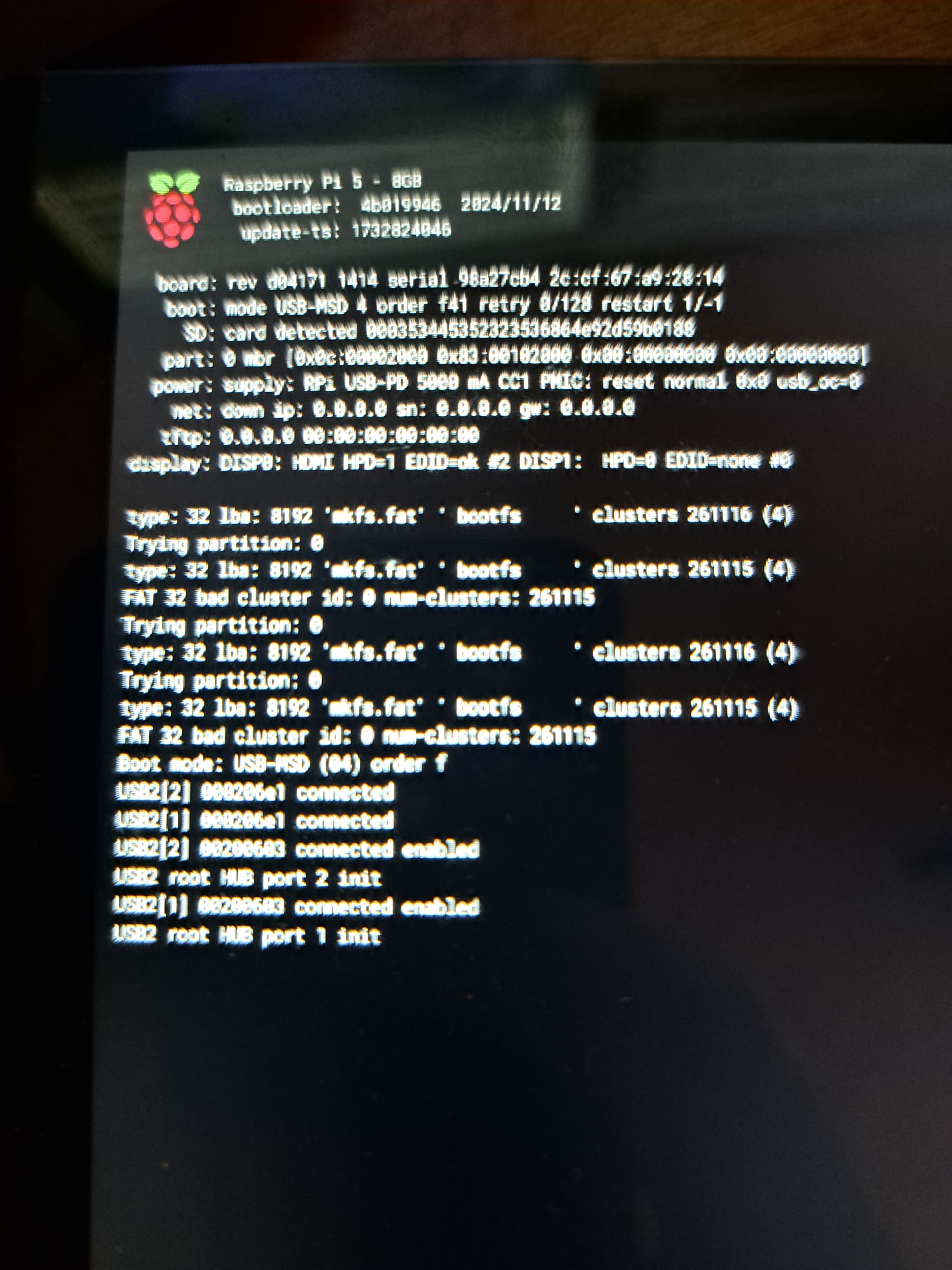
Burn the SSD again…
Next time I’ll not get a 256gb. You think its finished?
No it should re image ok.
It’s just what can happen if it’s updating or something similar when power is interrupted.
The card itself should be ok, and you should be able to just reimage it.
Even if it’s got data on it, it can sometimes still be got off as long as i’s not some important sectors on the disk or the data blat caught it while it was updating data.
Personnally I use 32G ssd’s. Seems the optimum sizes. Big one used to be a problem but I don’t think they are now.
Check you don’t have an intermittent short between pins on the pi with your wiring loom in place. That is the sort of thing that mucks up ssd’s
It’s getting nightmar-ish. Second fresh flash with the same output. Think a break would be good.
How did you do the fresh flash?
argh. I didn’t unpack it. Think I should really make a break.
1 Like
Take a break. The fact that the Pi booted as far as it did indicates the Pi is ok.
Fresh flash is working. So we have a status quo more or less.
Well Done.
It’s useful to see what can happen.
This is always an issue when playing with power supplies.
Are you calling it a night or wishing to continue?
Of course I wanted to have some success today. I rewired everything for better overview:
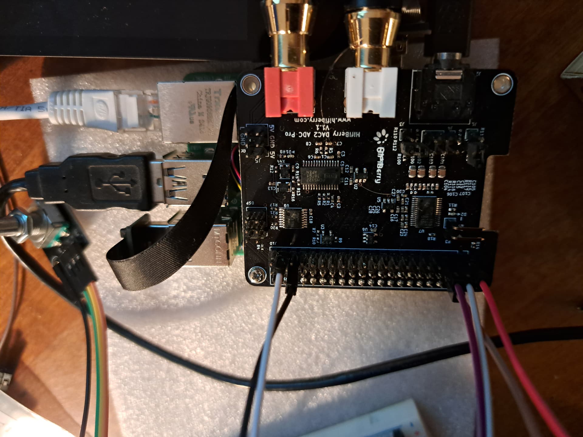
Mainly because the strength if the wiring just pulled the machine out of the breadboard.
BTW, you’re so kind. I must be one of so many people here taking your time.
1 Like
Start by getting just the power supply connected and confirm that the LED on the 23017 board lights all the time.
If I manage to put it in the right place the led is on.
So that’s something you want to get sorted.
Realistically a 40 pin edge connector and ribbon cable is the most reliable connector I’ve found. Push on pins behaves as you have seen.
Actually I cannot make it constantly be connected. I thought about soldering the mcp and some jumpers and pin headers I am sure about to the permaboard already so that I can just be safe about these connections. In fact the mcp seems to be not really connected all the time when just stuck on the two 13 pin headers on both sides.
AAah right you need to solder the pins on the board to the 17 way connectors. They aren’t connectors in themselves if that makes sense. they are just two pieces of metal touching each other at the moment from your picture…