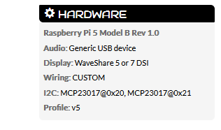
I’ve just added a second MCP23017 (this type) to my Zynth. The first has 4x encoders and 4x buttons and has worked perfectly for a while now. I can’t get the second MCP talking with the extra buttons. Both MCP are present on the main webconf page with the addresses showing.
I read these two threads and understand that I need to make some selection on the ‘Zynaptik Config’ drop down to reveal the settings to configure the second MCP address and interrupts.
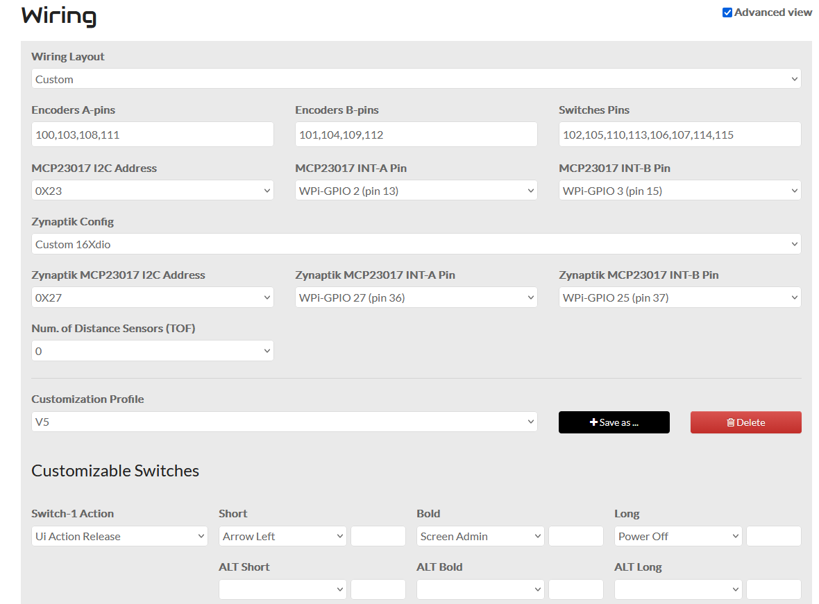
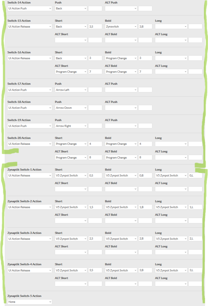
The pic is my config, I’ve configured the settings for the interrupt and the pins used for INT-A & B but it still doesn’t work. I also tried addresses x20 & x21 but no luck.
Some things I don’t understand:
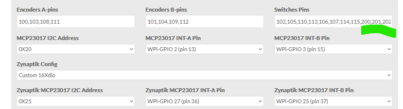
When a Zynaptik option is selected, does it mean I don’t have to use the ‘200,201,202’ etc. in the Switches Pins field? I notice when I do both I get more button config selections than I have buttons (switch options don’t do anything on the second MCP either way I try)
Does it matter which Zynaptik option is selected? I assume 16xdio is the one I want for the buttons
Can I choose any I2C address or does it have to be fixed at a specific number e.g. x20 for the first one with the encoders
Nice to know you are expanding your zynthian, mate. I hope i can help you with it.
In custom configs you have to configure your second mcp23017 as zynaptik.
First mcp23017 are configured in the 100 range while second one (zynaptik) pins have to be configured in the 200 range.
As you don’t have analog input/outputs, you should select 16xDIO.
You have to select the right I2C address for each mcp2317. Selection must match the hardware config.
I think you should not have Profile: v5 unless your hardware is an exact clone of the v5 hardware, and in that case you don’t need all the other settings. I think you want Profile: Custom or something like that to let your other changes take effect.
I’m confident that having the profile “V5” is ok, I guess the wiring layout is key here. I do have a custom layout using profile V5 because it is relying on the V5 onscreen touch pads.
This is the part I get a bit lost on. When I add 200-215 numbers and have zynaptik 16xdio selected, there are so many options for actions. One set is zynaptik switches and the rest are regular switches so I suspect one set is not required like you say. None of them activate anything unfortunately.
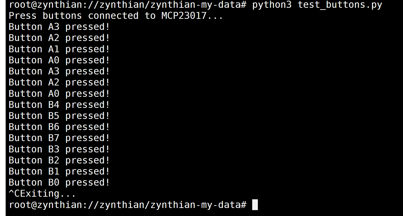
@wyleu Here’s the code for the button test script as created from AI, hopefully not leading me astray. The only thing I changed was smbus to smbus2 which is required for Pi 5 hardware from what I understand. This managed to register the button presses on both MCP chips when I tried both addresses separately (x20 & x21).
Summary
import smbus2
import time

# MCP23017 registers
IODIRA = 0x00  # I/O direction register A
IODIRB = 0x01  # I/O direction register B
GPIOA = 0x12   # GPIO register A
GPIOB = 0x13   # GPIO register B

# I2C address of the MCP23017
MCP23017_ADDRESS = 0x21

# Initialize I2C (bus number may vary depending on your setup)
bus = smbus2.SMBus(1)

# Initialize MCP23017
bus.write_byte_data(MCP23017_ADDRESS, IODIRA, 0xFF)  # Set all pins on port A as inputs
bus.write_byte_data(MCP23017_ADDRESS, IODIRB, 0xFF)  # Set all pins on port B as inputs

try:
    print("Press buttons connected to MCP23017...")
    while True:
        # Read GPIO registers
        gpio_a = bus.read_byte_data(MCP23017_ADDRESS, GPIOA)
        gpio_b = bus.read_byte_data(MCP23017_ADDRESS, GPIOB)

        # Check button presses on GPIOA (0-7)
        for pin in range(8):
            if not (gpio_a & (1 << pin)):  # Active-low logic
                print(f'Button A{pin} pressed!')

        # Check button presses on GPIOB (8-15)
        for pin in range(8, 16):
            if not (gpio_b & (1 << (pin - 8))):  # Active-low logic
                print(f'Button B{pin - 8} pressed!')

        time.sleep(0.1)  # Debounce delay

except KeyboardInterrupt:
    print("Exiting...")
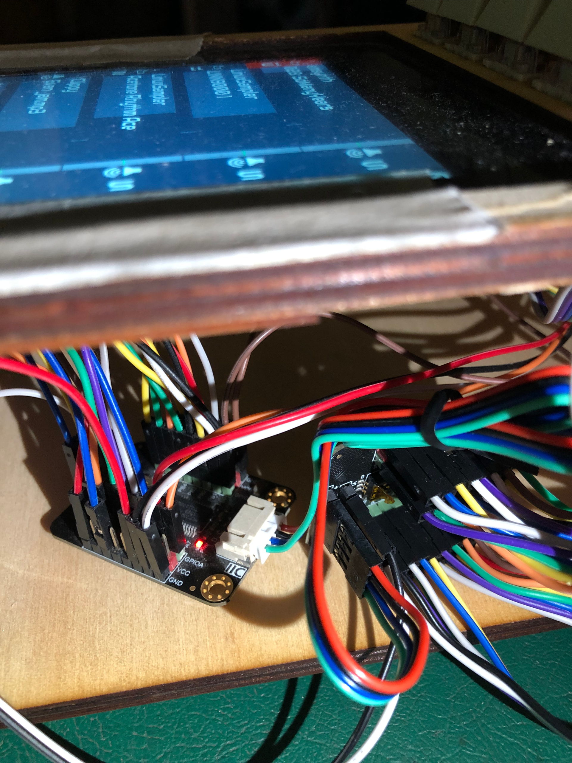
Some other things to note if it matters is that I’m trying to get this configured on Vangelis testing and the second MCP daisy chains from the first with the included cable. I don’t think that’s causing an issue because the button test is successful.
I’ve been checking and you should not specify the zynpatik pins. They will be auto-asigned from 200 to 215. Trying to configure these pins will cause trouble,
In other words, you must configure the switch pins only for the first MCP23017, where encoders and switches are connected together, so you need to specify what pins are used for encoders and for switches. The second MCP223017 is configured as zynaptik and pins are auto-asigned.