EDIT
I wired it and make Prototipe 1 config like this:
Encoders A-pins: 3,4,15,18
Encoders B-pins: 17,27,25,8
Switch pins: 2,14,22,7
The other MCP default and the last empty.
Only works the 1st encoder down and the clk
EDIT
I wired it and make Prototipe 1 config like this:
Encoders A-pins: 3,4,15,18
Encoders B-pins: 17,27,25,8
Switch pins: 2,14,22,7
The other MCP default and the last empty.
Only works the 1st encoder down and the clk
Actually doesn’t work and can’t connect to the Zynthian. DHCP doesn’t works. No web and ssh access.
09-16-2020
09:45:12
Successfully assign IP [192.168.0.17] to client mac [dc:a6:32:11:c2:c4], lease time [86400]
LAN
09-16-2020
09:45:12
Received REQUEST from client ip [0.0.0.0] mac [dc:a6:32:11:c2:c4]
LAN
09-16-2020
09:45:12
Send OFFER of ip [192.168.0.17] to client mac [dc:a6:32:11:c2:c4]
LAN
09-16-2020
09:45:11
Received DISCOVER from client mac [dc:a6:32:11:c2:c4]
EDIT:
Pushing back key on start I recover it and now works webconfig.
On web midi test only works this on all the controllers wired.
CH#01 CONTROL_CHANGE 71 => 0
CH#01 CONTROL_CHANGE 71 => 0
CH#01 CONTROL_CHANGE 71 => 0
CH#01 CONTROL_CHANGE 71 => 0
CH#01 CONTROL_CHANGE 71 => 0
CH#01 CONTROL_CHANGE 71 => 0
Some help here? What’s the right order of the wires on web config?
Try:
Encoders A-pins: 4,27,15,8
Encoders B-pins: 3,22,14,7
Switch pins: 2,17,18,25
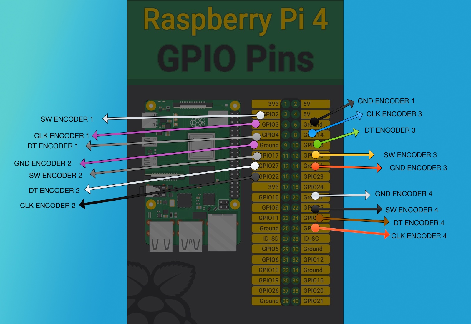
You don’t make it easy, hiding the GPIO numbers in your picture and using different colour arrows for the same parameters  .
.
I use the color of the wires. Yes my pixelmator skills are bad 
doesn’t work with custom or prototype 1.
on midi router only the 4 encoder sends messages:
CH#01 AFTERTOUCH 0
CH#01 AFTERTOUCH 0
SYS RESET
SYS RESET
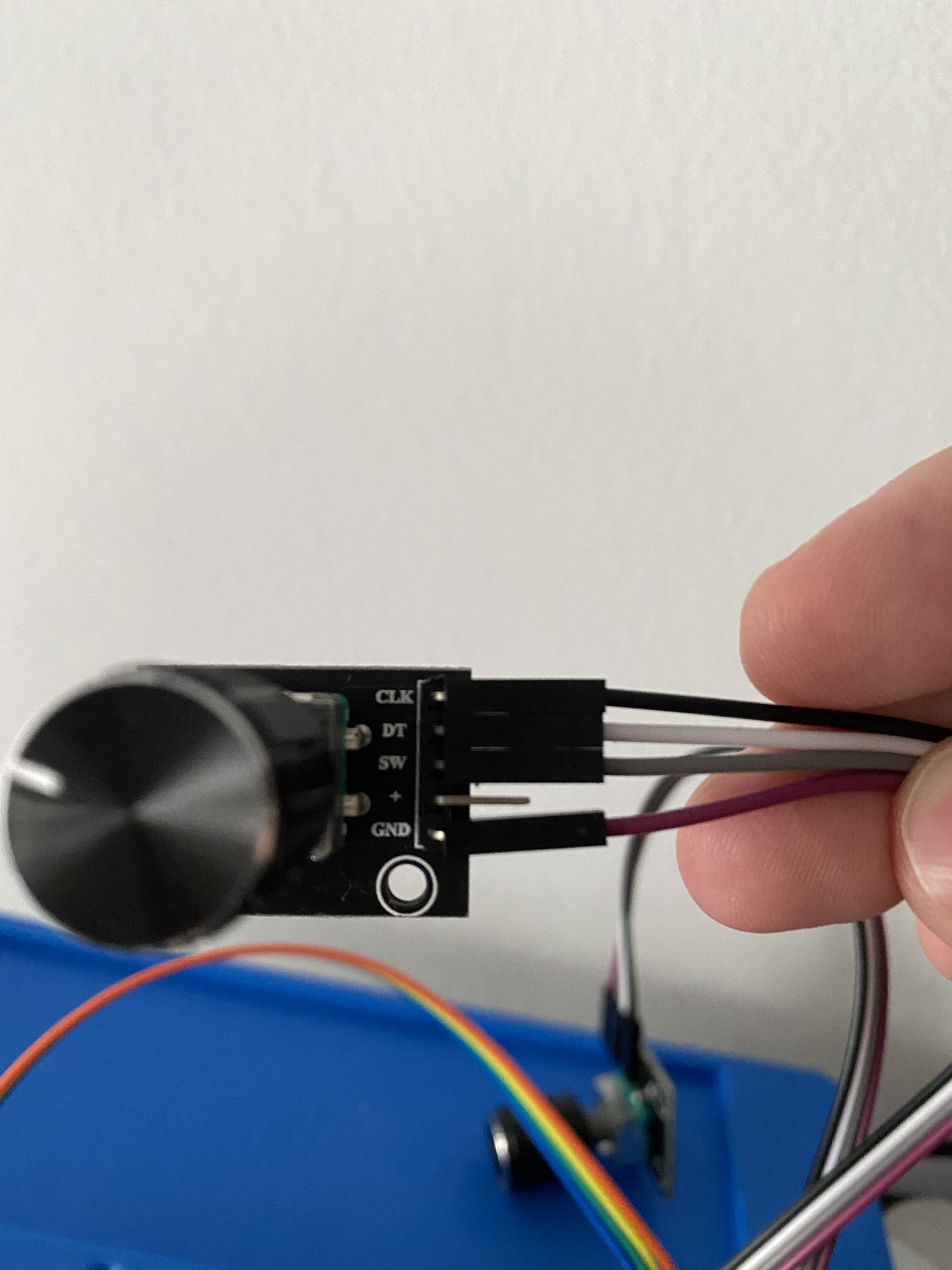
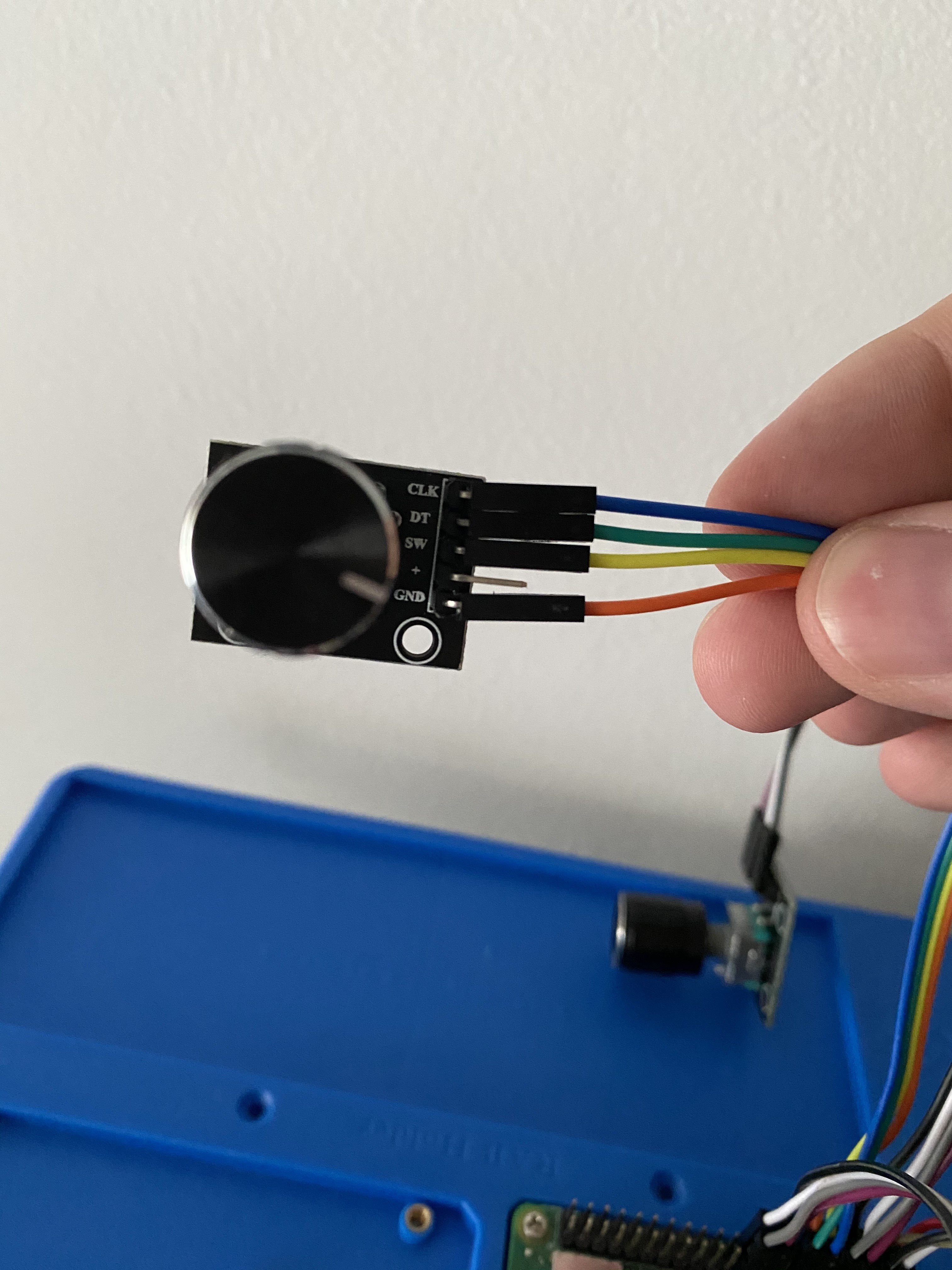
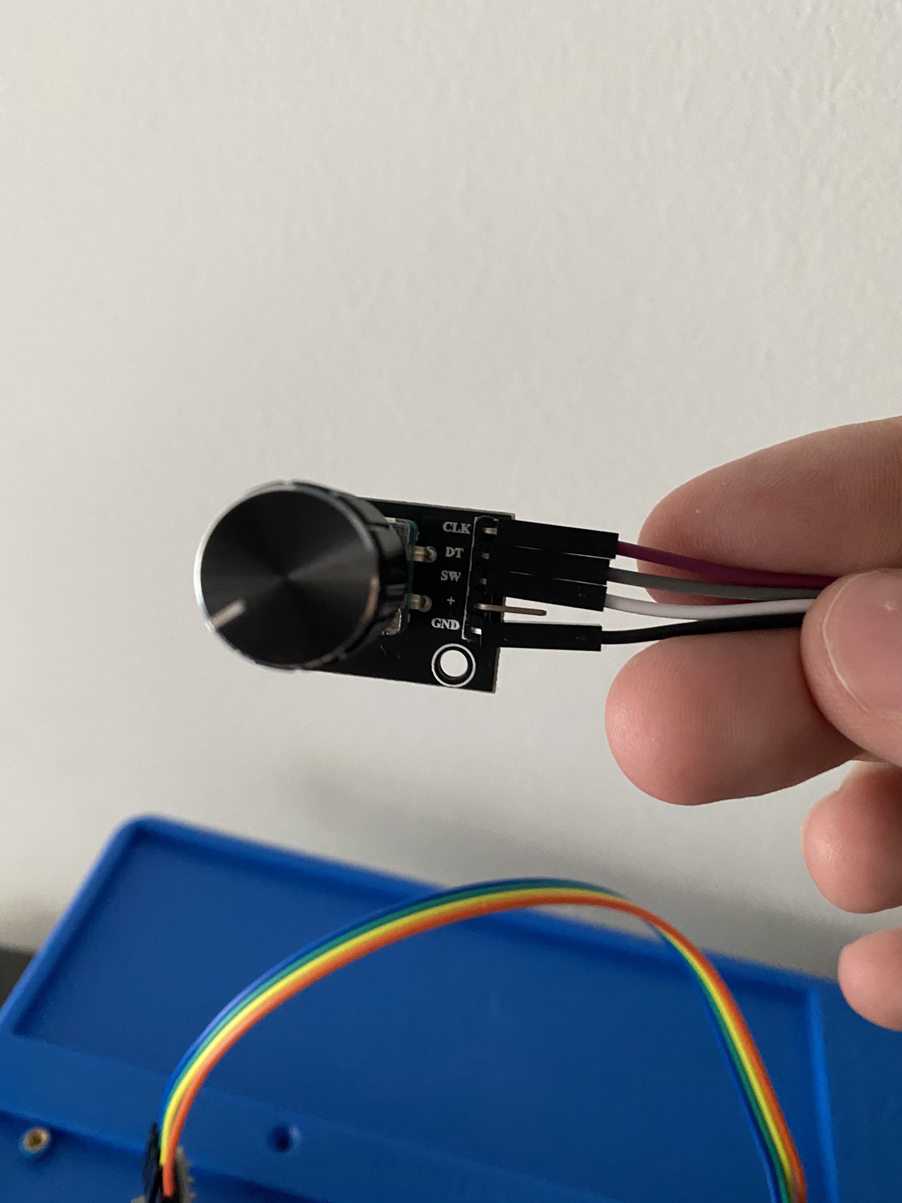
I’m so confused. Which correspond to clk and which to DT on my key-040  . I need to find this to wire all like you do and see if works.
So complicated this gpio thing.
These rotary encoders use a quadrature encoding. In their rest state both signal pins are disconnected. As you turn the shaft, the common (ground) pin is first connected to one signal pin, then both pins then the first signal pin is disconnected and finally both are disconnected as you return back to a detent. The Zynthian decodes this to detect direction and rotation, one detent at a time. The “Clk” and “DT” pins are actually just these two signal pins. As long as you connect ground to the common pin and each signal pin to a GPIO then assign the pins in the webconf it should work. It is possible that it will work in reverse if the pins are reversed but that is simply resolved by reversing the configuration in the webconf. The switch is activated when the shaft is pressed connecting. This needs ground on one side and a GPIO on the other.
Checkout the link that @wyleu posted. He has made this work.
Yes. THe major confusion is the Numbers we refer to from within the webconf display.
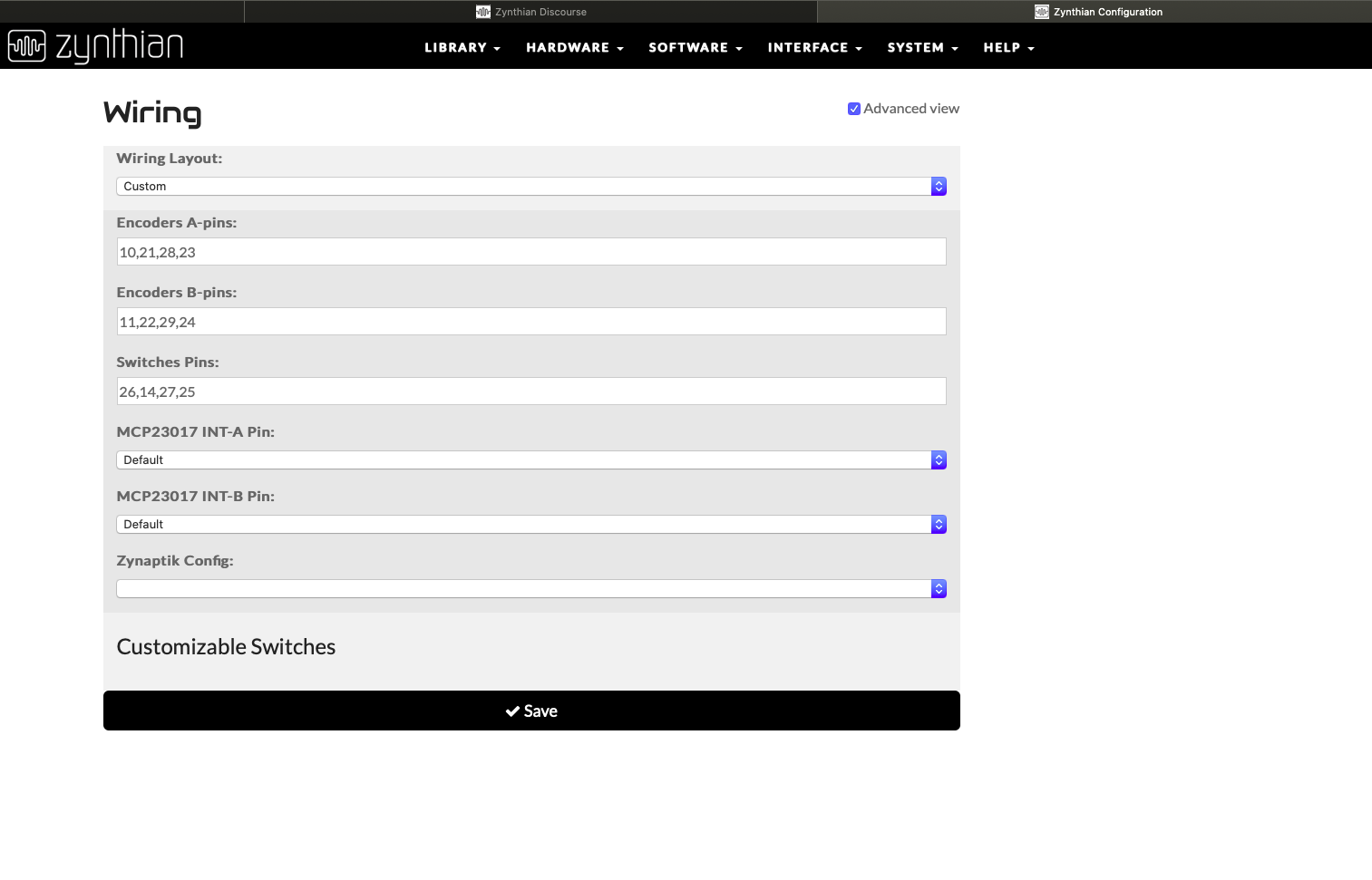
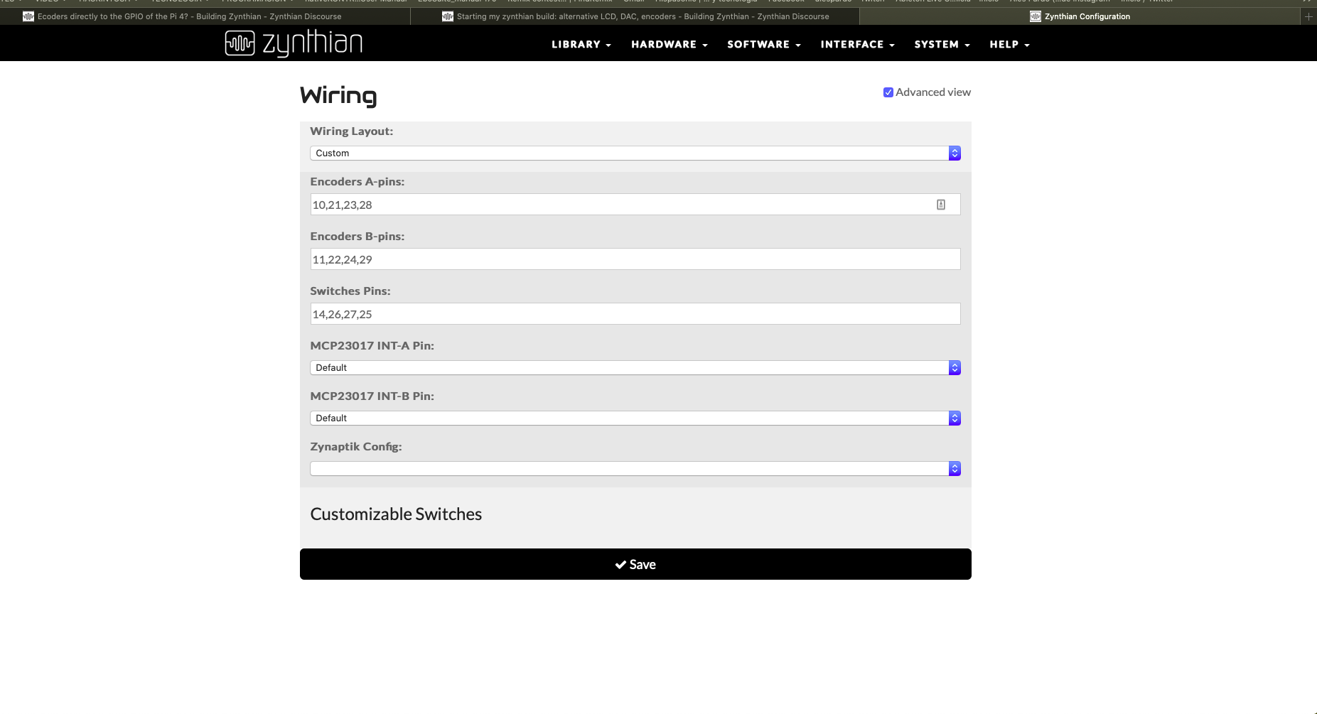
This is the webconf of the machine (zynthian-ceed.local) using the wiring described. It’s my dev machine which gets all kinds of abuse.
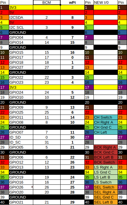
As you can see it refers to pins and the interrupts. but these numbers refer to BCM column in the chart which then need mapping across to the PIN’s on the GPIO connector.
Course the Raspberry IO pin connector is a standard that has been adopted all over the place so it all gets more confused. But If I wanted to use the chip to make my own machine without an IO connector I could and that’s why software writers do it this way.
It does work!
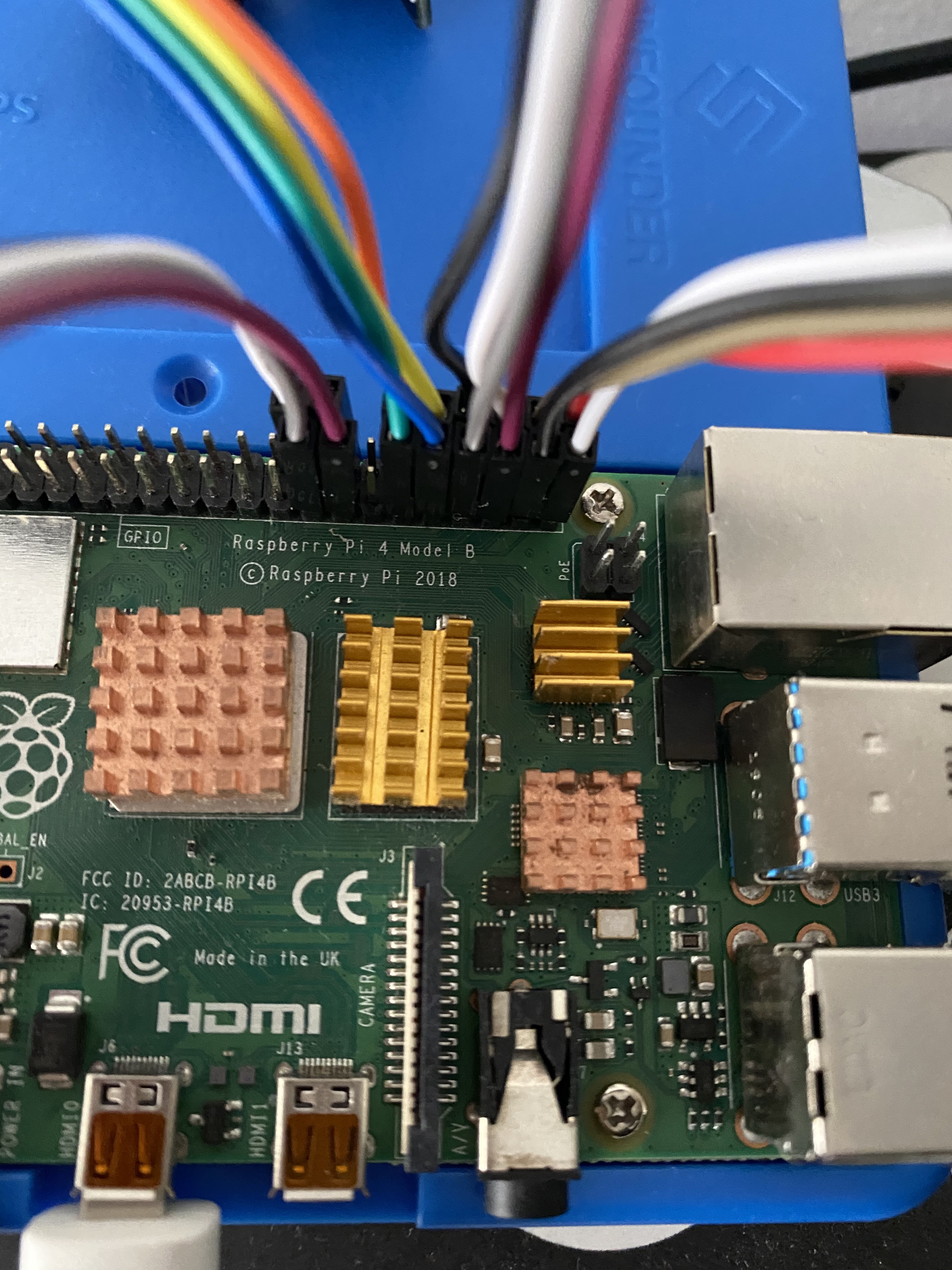
Here’s the advantage of all this mucking around. As you can see in this machine space is very tight and laying the ribbon cables like this it allow it all to be assembled. I can then use the mapping to just choose the relevant pins on the PI that these connect to. Software flexibility saves space in the box !! ![]()
Hi, sorry the delay but I was taking care of my son these days.
I wire the 4 encoders on the GPIO like on your schematic. The thing is with the web config, I tried cloning your photo configs but doesn’t works.
Tryed too putting the BCM numbers but doesn’t works too.
With your photo configs only works fine the switches. No one encoder can turn ok any parameter of any Zynthian layer.
I don’t get why the WPI and the BCM.
To be clear, I wire the pins physical on the GPIO numbers and then on the web config put the WPI numbers of all the wires. But all works like the switch Zynthian option of the encoder. If I push it works but if I turn the encoder makes the same thing like pushing it :S
I
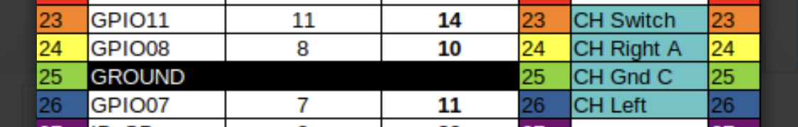
The first encoder wired on physical pins 23 SW (click or switch), 24 DT (pin A), 25 GND and 26 CLK (pin B). This encoder only transmits “back” on the zynthian, the click and the encoder in booth ways.
The second encoder wired on physical pins 29 DT (pin A), 30 GND, 31 CLK (pin B) and 32 SW (click or switch). This encoder only transmits “layer” on the zynthian, the click and the encoder in booth ways.
The third encoder wired on physical pins 33 DT (pin A), 34 GND, 35 CLK (pin B) and 36 SW (click or switch). This encoder only transmits “learn/shot” on the zynthian, the click and the encoder in booth ways.
The fourth encoder wired on physical pins 37 SW (click or switch), 38 DT (pin A), 39 GND and 40 CLK (pin B) . This encoder only transmits “select” on the zynthian, the click and the encoder in booth ways.
I just don’t understand how is the comparation with the webconfig and the physical on the PI.
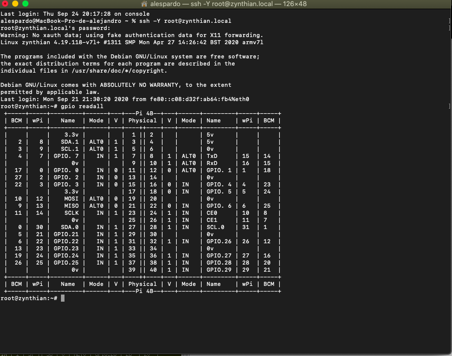
have you ssh access to the zynthian …?
I can’t remember the name of the command line utility ( gpio readall… details in Encoder mapping for Direct I/O connection ) that will show you the actual status of the pins on the Pi…
ModMyPi MCP23017 pHAT is another thread with some encoder details. Are you sure the switches on the encoders are wired to zero? I’ve had some odd connections on them…?
Thanks for the pictures and detailed connection details. I can see the issues…
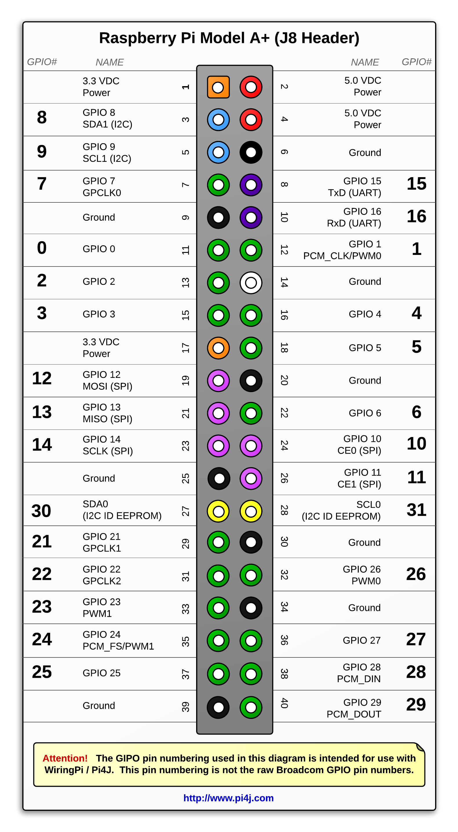
First you must use the WiringPi numbering scheme, not the BCM scheme so use these numbers:
I have tested each of the following GPIO and proven they all work so you should be able to wire to any of these for switches / encoders: 8, 9, 7, 2, 3, 12, 13, 14, 30, 21, 22, 23, 24, 25, 1, 4, 5, 6, 10, 11, 31, 26, 27, 28, 29.
If you intend to use I2C for anything (now or in the future) then avoid using GPIO 8 & 9. If you intend using I2S audio then avoid using GPIO 1, 24, 28 & 29. If you use GPIO 9 for a switch contact then you can use that switch to turn the Zynthian on from its standby state (off but power applied, e.g. after a manual power off). You may wish to avoid using GPIO 30 & 31 which are used by Raspberry Pi to access onboard EEPROM.
Here’s the shot of the ssh
What i read on the other thread is the people desolder the resistors of the encoder
Finally I could to test the resistors removal from KY-040 and like @masterkey told previously, worked like a charm. Now I’ve three things to do: build the case, build an arduino based usb-midi controller and maybe upgrade the raspberry to latest version (3B+). The zynthian gorgona image most recent works with raspberry pi 3B+?
I change the web config with your numbers, now all the encoder switchs works like they need to do. But the encoders still making the same thing like the switches.!
But the encoders still making the same thing like the switches.!
Watch gpio readall when pressing the encoders.
You should see activity on two GPIO input pins when you turn an encoder and one GPIO input respond when you press the encoder switch. Sometimes this can be hard to do without turning the encoder slightly.
I don’t understand what you mean.
Have you rewired encoders to match your new webconf configuration?
Do all 4 push switches operate as expected?
What are each of the rotary encoders doing when you rotate in each direction?
Yes the encoders make the same thing like the switches. On both ways.
zynthian gpio (17.2 KB)
I move the encoders or push the switch and run the comand but all stills the same.
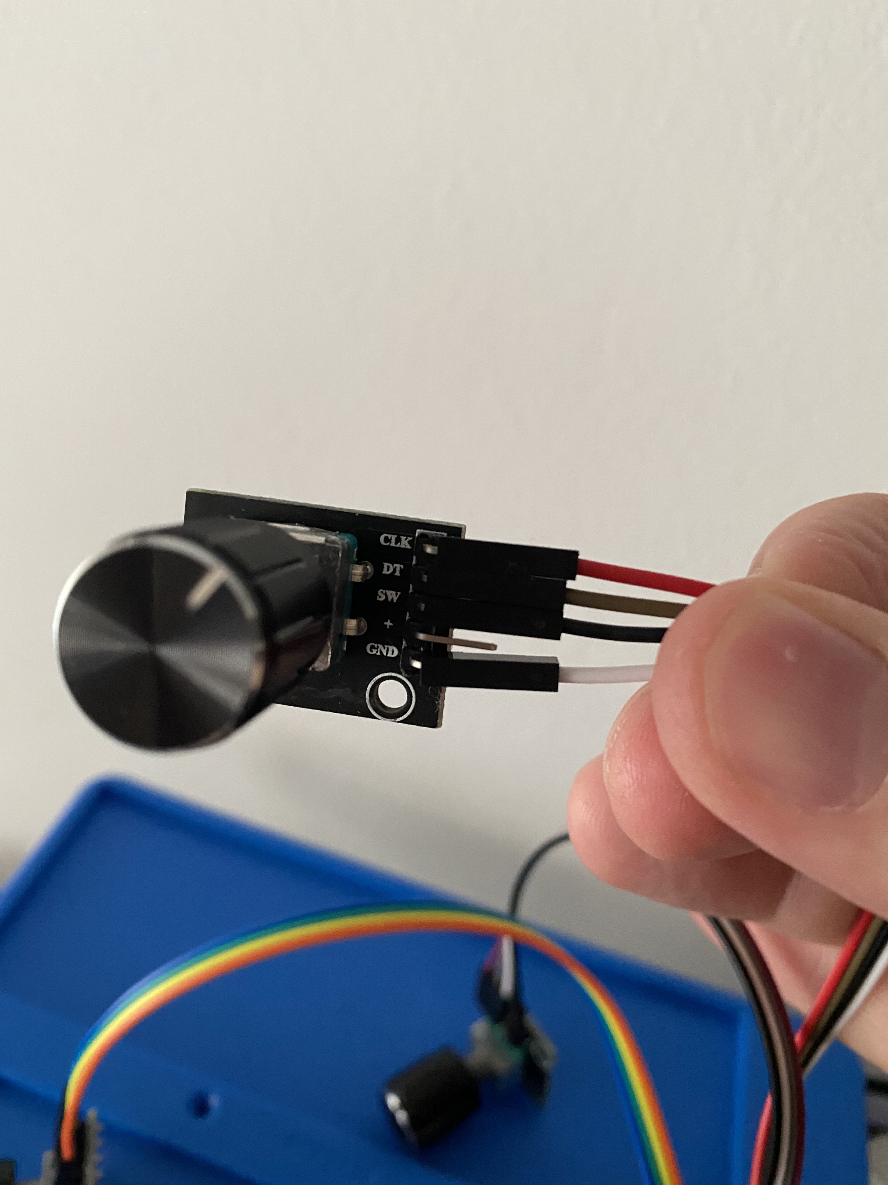
I change the mistaken numbers on webconfig acording your photo. The wires i think are ok on the GPIO there’re pined right?
The switches working fine, the problem are the encoders. They act like the switches on both ways.