I’m working on how to put together a zynthian v5 with thru hole components and breakouts (for things like the mcp23017). I think it’ll make an interesting and very modular version of the hardware that will be great for tinkering with code and new hardware configurations. My question is, in the zynthian_hw files, what is the difference between v5_control and v5_control-rack? Is rack shorthand I don’t know? Why are there two versions of what appear to be the same schematic?
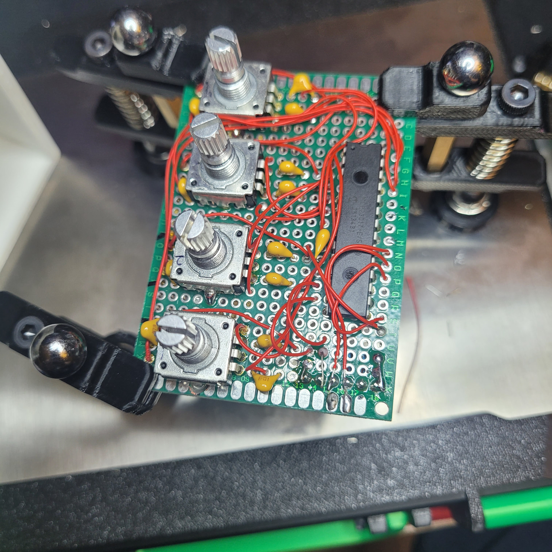
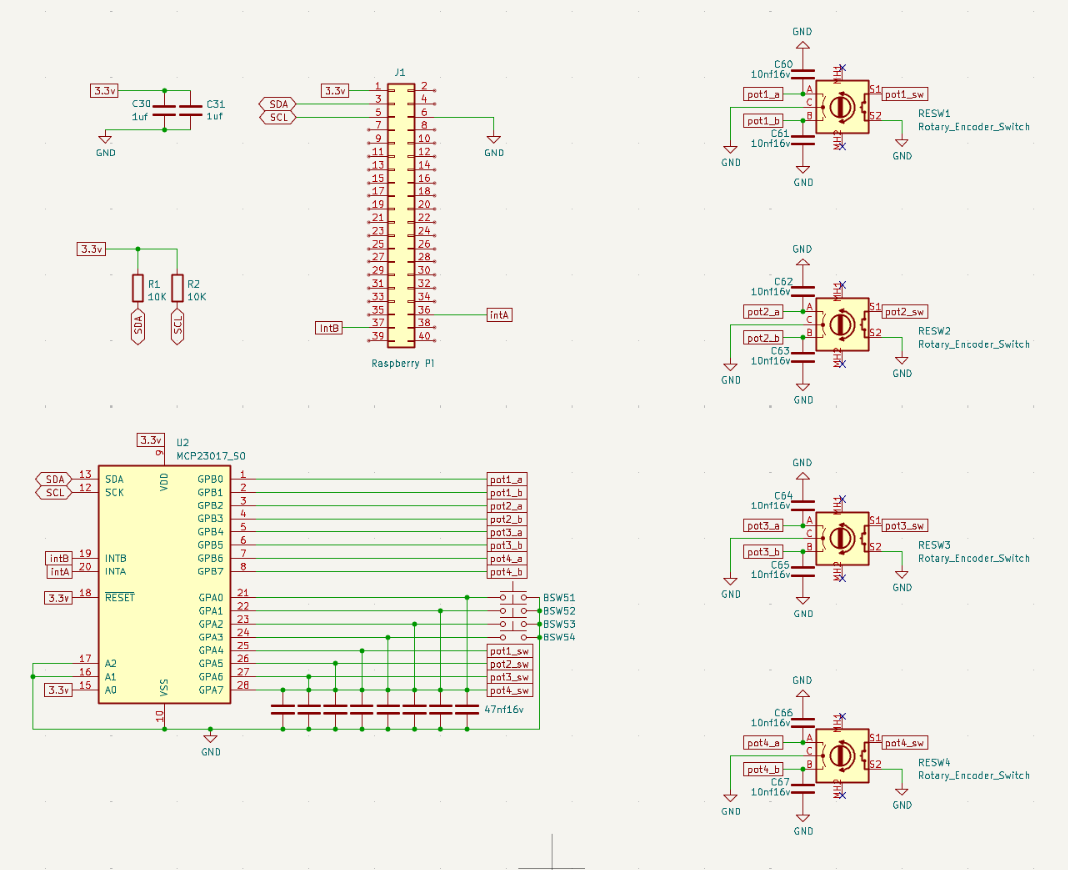
I just made my own encoder panel using the through hole dip package of the chip. Be aware that the schematics in the git use the surface mount package that has a different pinout, so be sure to reference the data sheet of the mcp23017. I almost miswired mine. If I’m at my computer later I’ll upload the modified KiCad schematics for the dip package.
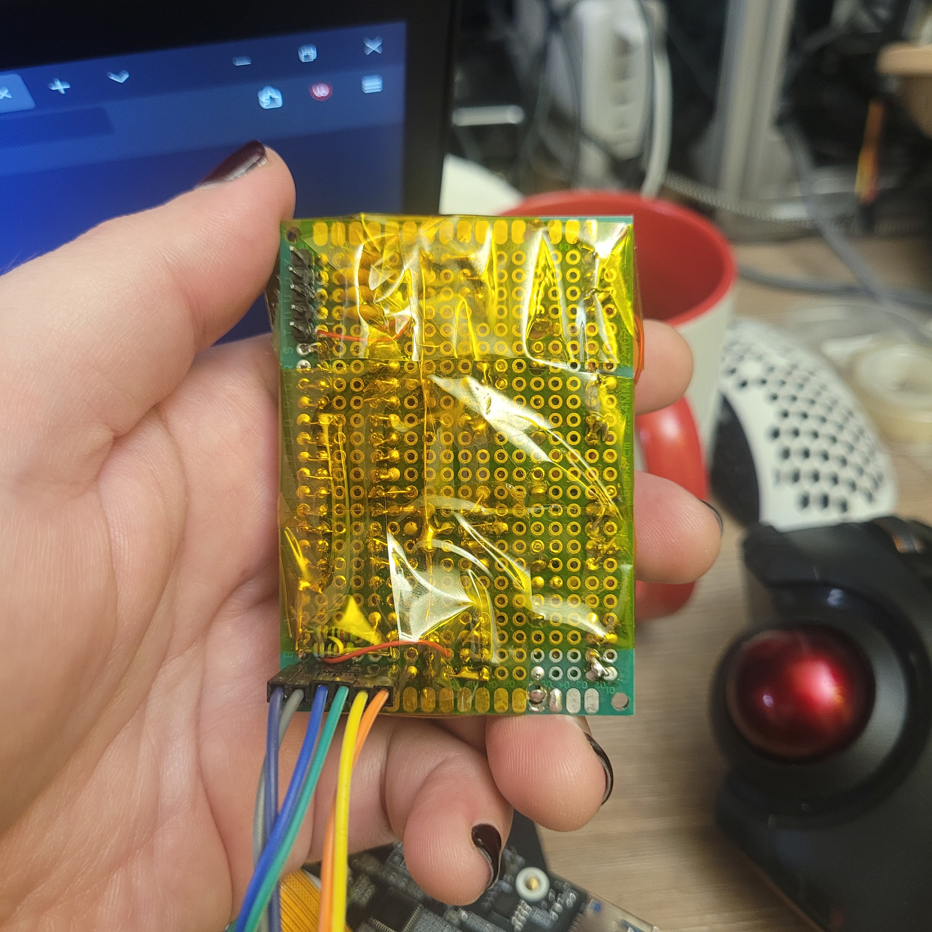
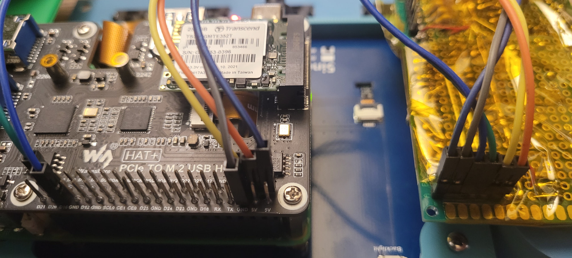
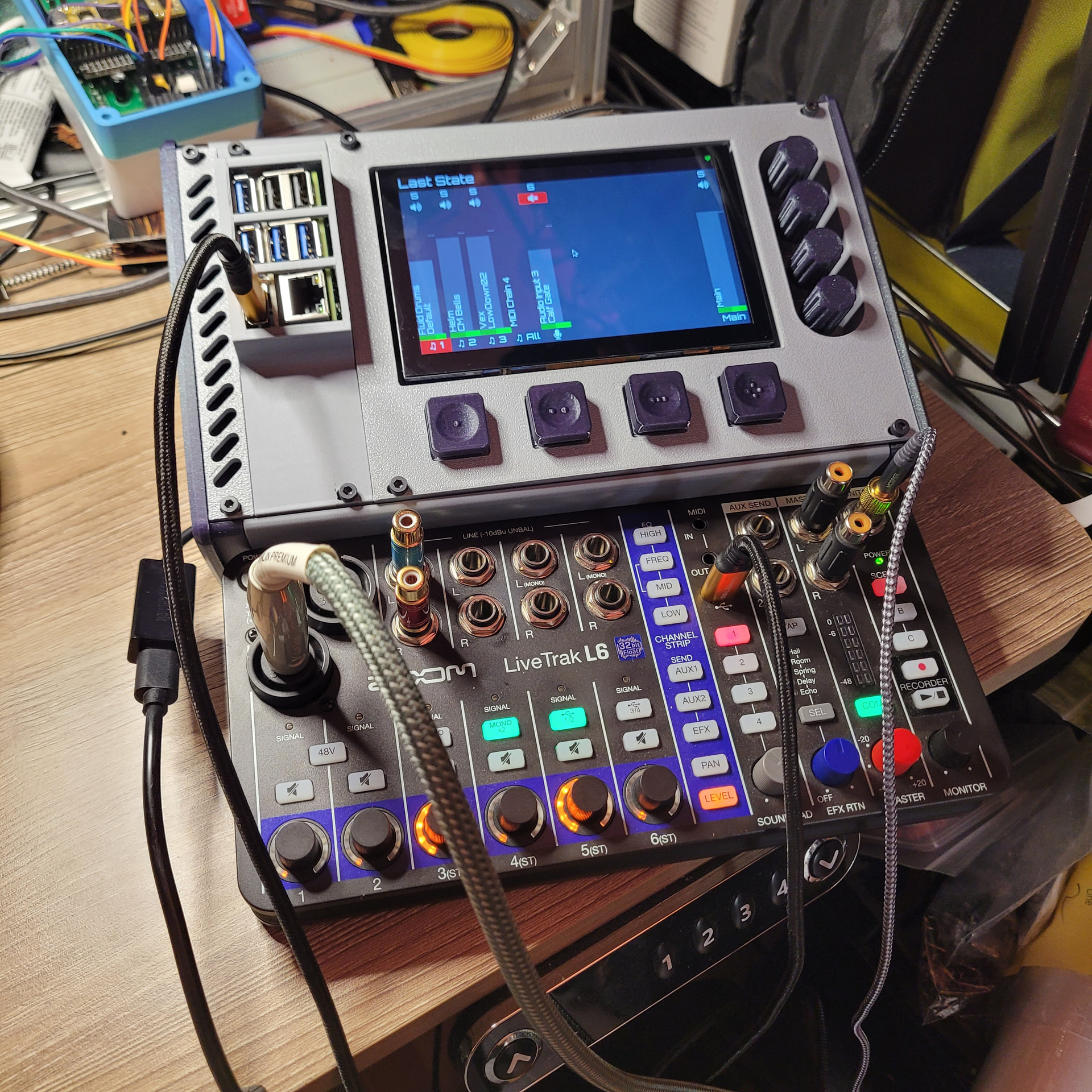
Here you go. Not much happening on the back and I already wrapped the board in kapton tape.
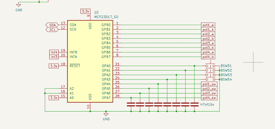
And here’s my modified schematic pinout as well. It fully works, but it took me quite a bit of twiddling to get the hardware settings correct. (That settings page makes no f cking sense at first, and second, and most of third).
I’ll upload a screenshot of that at some point. My zynthian is currently on pieces while I’m designing and 3d printing a housing for it.
Oh yea, also I broke out the pins for the 4 bottom buttons so they can be hand wired and just have a header connector to plug in to for modularity. So that’s what the other 5 pin connector is on the back of the board.
Lol, yea. I knew I’d be handling it a lot while getting it working and getting it into a case. Also the chip edge of the board is going to be under the screen with the encoders butted up the side of the screen and I didn’t want anything to short on the housing. I’d just bought a couple spools of it so could afford to be extra.
Fantastic! As soon as I finish the move and my lab is up and running, I’m volunteering to mill a PCB with my CNC machine. Naturally, no SMD components, just through-holes like in the good old days.
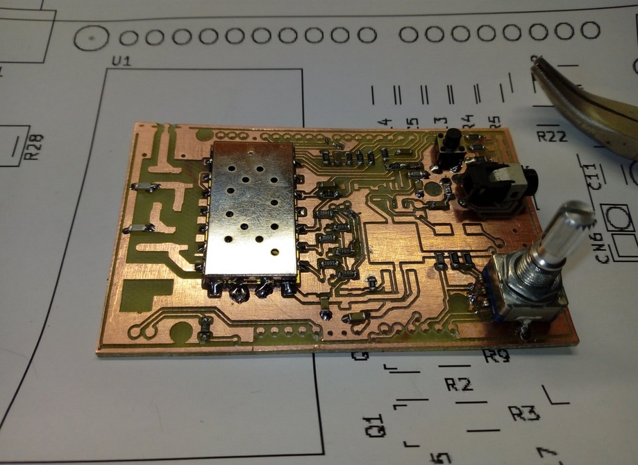
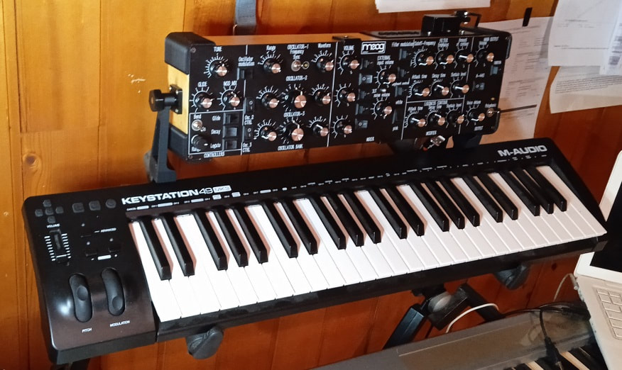
Hi. I’m in the process of making my own encoder panel board, too, as part of a bigger project (yet-another minimoog synth MIDI controller - @lanfranco: I saw yours, but decided to go for a much smaller footprint).
It’s a “daughterboard” to add rotary encoders to a bigger board with lots of potentiometers and switches. I’m posting it here since I decided to add ARGB leds as well. I’m not sure what they can be used for, but there they are. I’m now waiting for the PCBs to sail from China.
This is the render of the daughterboard. It connects through a 7 pin header to my synth main board, but I plan to connect it to Zynthian too (it’s I2C plus power, signal and int).
I saw yours, and I’d love to have it. But from checking the posts where you explained the process, I understood that sourcing all the components and builiding it would be far more complex (and expensive). I then saw maasijam’s build and thought that forking it would be easier.
Once I succeed in building the firmware for RPico, I’ll maybe post my build in another thread here.
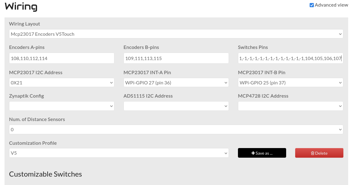
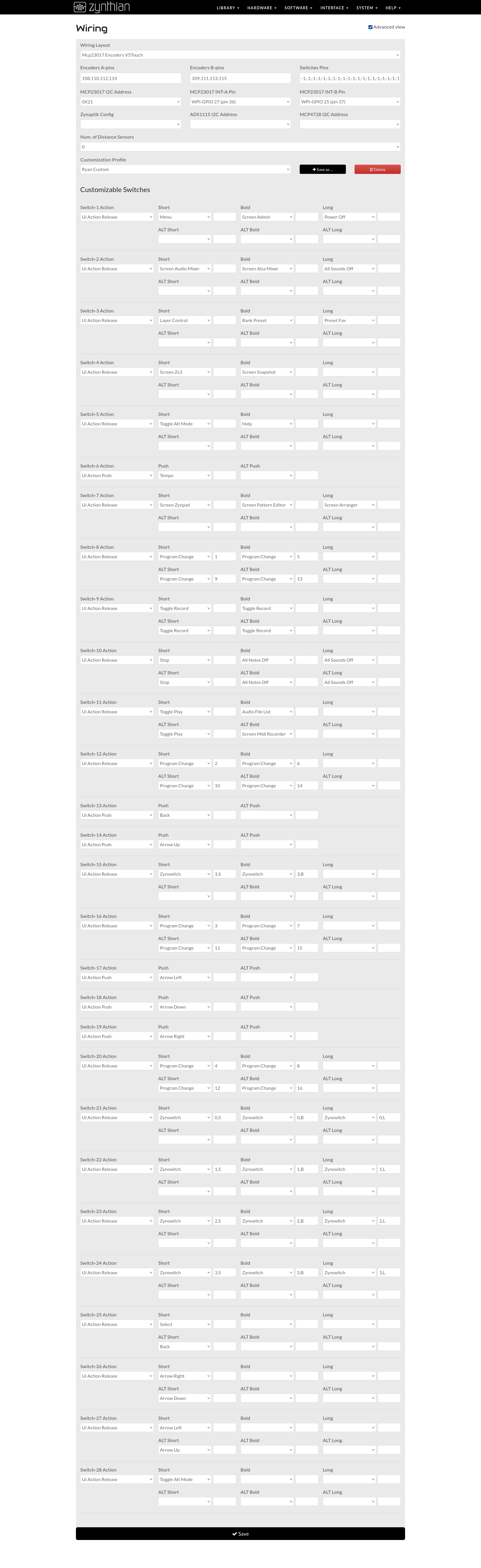
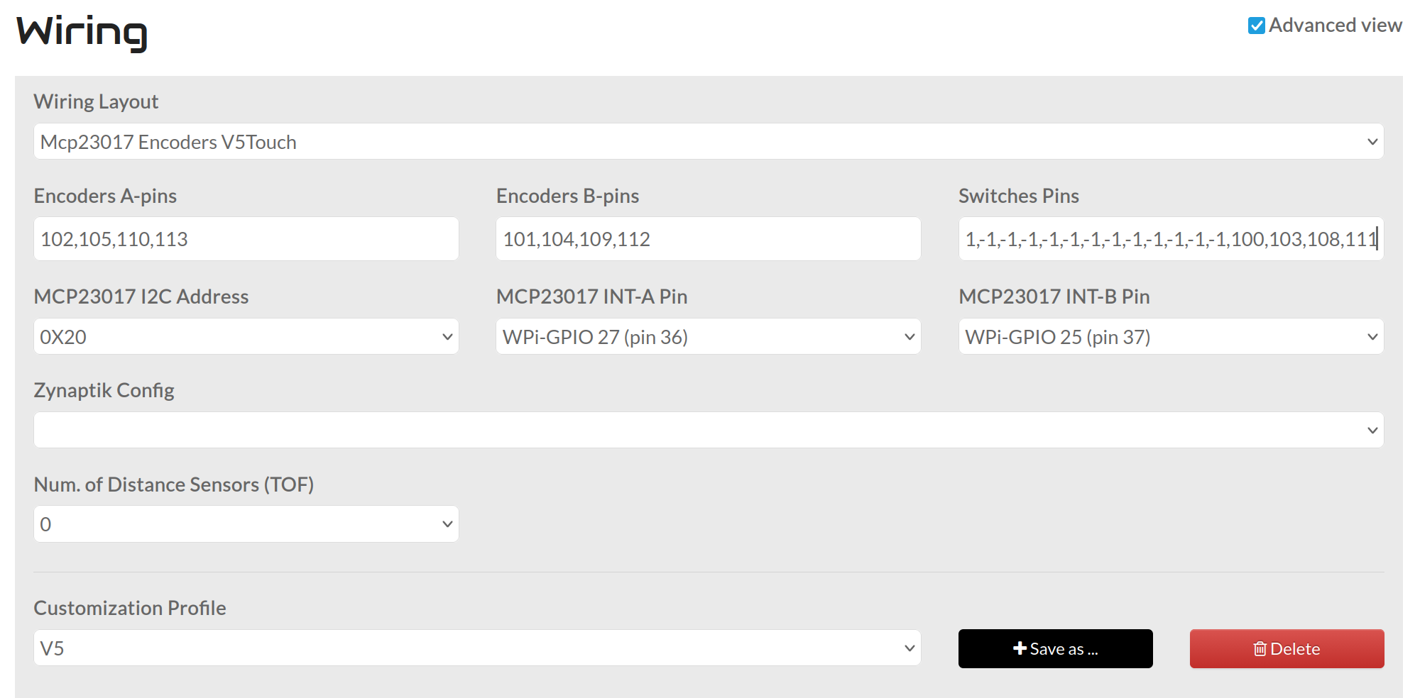
Sorry for the delay, but also here’s the wiring page. This was one of the more surprisingly difficult parts as the wiki felt very unclear on how to set this up.
Hi,
I only saw your post today.
I have been struggling with the configuration for some time now, and it is not yet finished.
Mine was working with encoders only, but not yet for encoders + 20 buttons
Is yours running now?
Maybe it is of interest for you that, on my suggestion, jofemodo added a Zynaptic config possibility to the staging version:
I only have the 4 encoders(and their buttons) and the 4 key-switches hooked up, as I’m only using a single mcp23017, but everything is working just fine for me, so at least my current configuration and wiring are proven out for me.
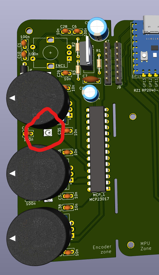
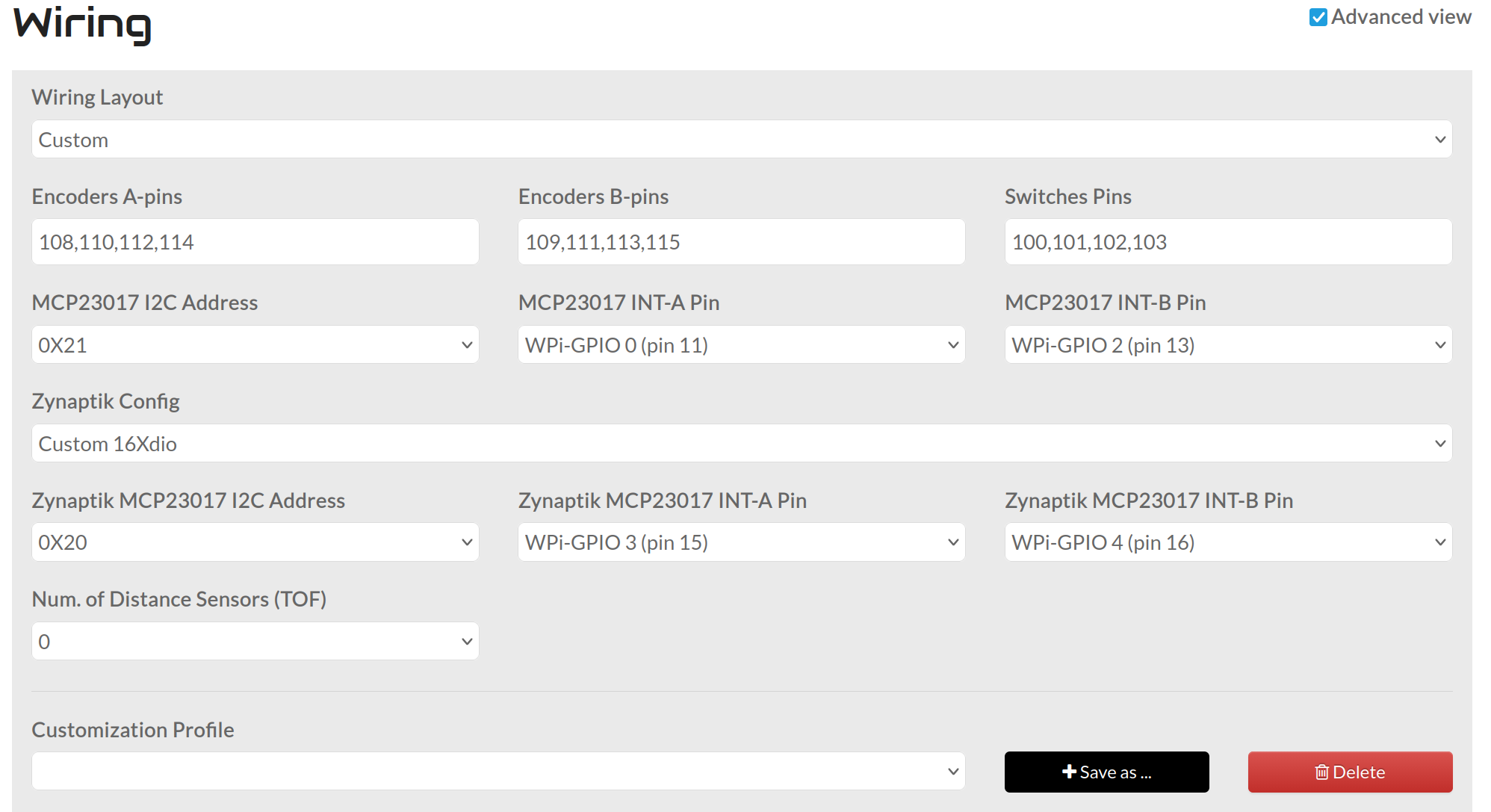
As far as the full 20 buttons, are the 4 buttons hooked up to your first mcp23017 working? For me my “Switches Pins” looks like this:
Where 104,105,106,107 are my encoder pushbutton and 100,101,102,103 are my mechanical key-switches(In reference to the schematic below).
For your other 16 switches I’m pretty sure you’ll need to add their pinout to the “Switches Pins” section in place of where I have all the “-1”. The -1’s allow use of the V5 Touchscreen controls.
The main issue that I can’t find any info for, is what that pin numbering would be for a second mcp23017. I saw in your other thread that they might be numbered 2xx, so that’s the route I’d go.
If you have it wired the same as a default V5, and the 2xx convention is correct, I think it’d be
Below I have a screenshot of my “Wiring Config”, everything is for config of the V5 Touchscreen controls and the bottom 4(Switch 25,26,27,28) correspond to my added mechanical switches(100,101,102,103).
(There are 20x -1 for the switches pins)
My inspiration for this came from the example Buildin_a_custom_Zynthian in the Wiki.
OK, now I would expect this to work also when I change the wiring to CUSTOM, shouldn’t it?
Why V5_TOUCH (it was set so in the wiki)
This makes no sense for me.
As I’m really missing something concerning the information, I have done a dive into the source code and the structure of Zynthian (My God, it is complex! Waht a piece of work! Congratulations for the authors!)
I found these debugging methods very useful:
connect via SSH and do dmesg (→ general Linux errors)
install Midnight commander (mc), so you can easily browse the file system
tree in /zynthian gives the whole file structure (gigantic, you have to filter)
uncomment some of the fprint statements in /zynthian/zyncoder/zyncontrol_vx.c and recompile
view the debug log in the web interface
I don’t know if the 200 convention is correct, jofemodo could tell us.