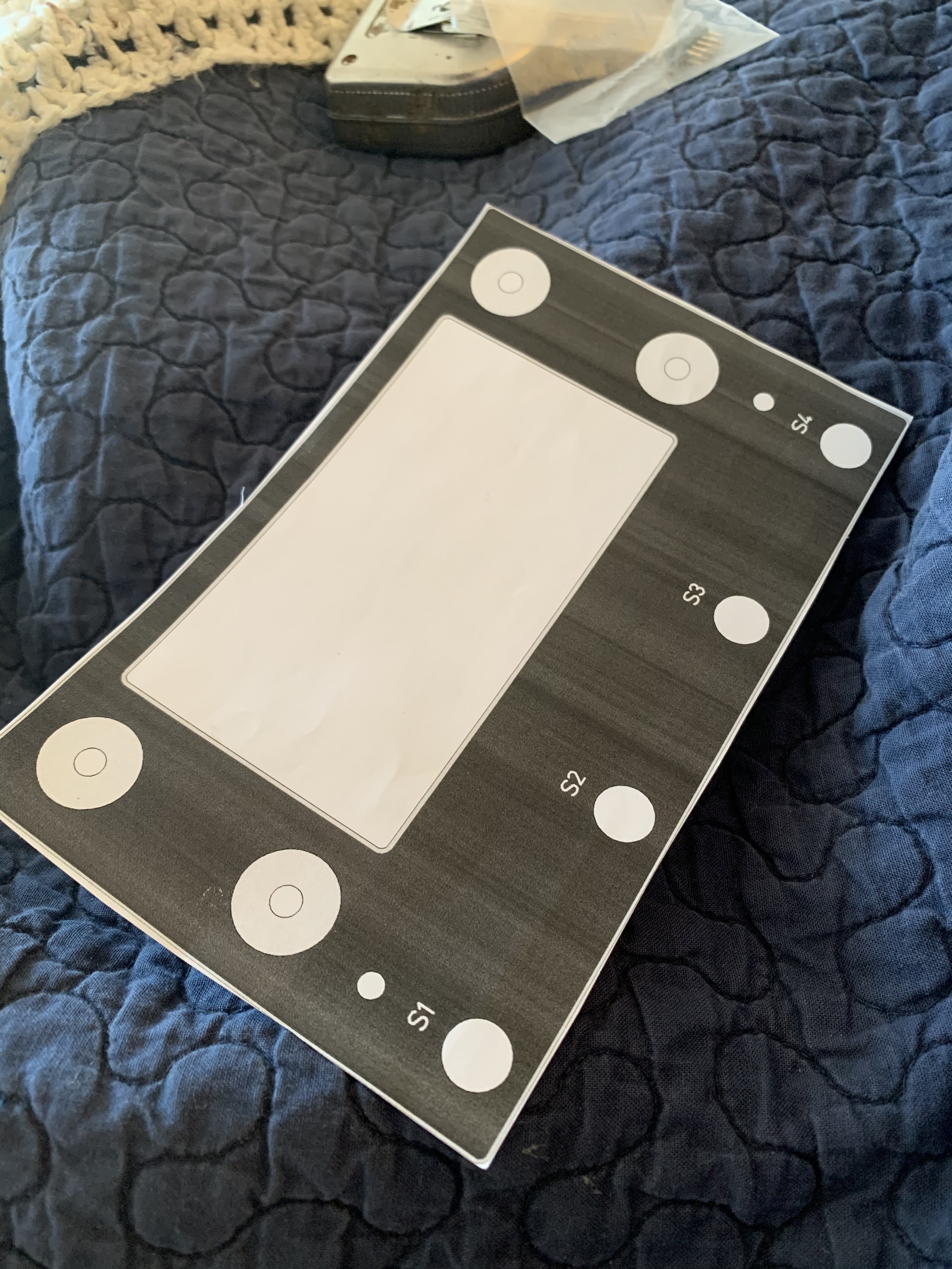
EDIT: Ah, found the breakout for S1-S4 in the wiki
Need to look into LED activity for when it is pressed.
I’m sorry if this has been asked before but instead of using the silicone buttons s1-s4 of the v4.1 display kit I would like to add 4 x momentary stomp box pedals (spst) in its place. Is there a breakout point on the connection board?
I also have some “tough duty encoders” form an older pedal project that used them as footswitches to save space that I’d like to use for the regular knobs). Generally I’ll be using some rugged panel mount parts but my hope is to build one tuff-little-unit to replace a large and heavy pedalboard full of FX down to just a couple… or one!
I don’t want to use the zynthian kit screen and instead hope to choose a physically larger 6” display type because footpedals imply a greater distance. It’ll be angled to face me on the board’s incline.
Case I think will work is 1590DD ( 188 x 119.5 x 37mm)
There are four available input ports for switches on the allinone encoder boards ( the later versions) and these are as you say allocated to the s1-S4 keys in most implementations. You can also add the zynaptiks board Using Zynaptik module for encoders [SOLVED!]
to gain four more digital pins which can be configured as ins and outs along with analog in & out, but this is still up for definition,. IT’ adds on as another 12c port so short wires are probably the order of the day between the boards.
As to pedal boards there is my zynthian saga of long standing, admittedly a diferent meaning of pedal board but a lot of the observations might be relevant. A pedalboard zynthian .. .
Which has explored a lot of the aspects you are describing.
I’m keen to bring a control panel out at standing hand level as I’ve always hated scrabbling round on the floor adjusting pots and driving menus on devices like the Roland loop pedals and such like.
However I do think a touch screen on the pedal end is useful. I have looked at using 4 + 4 momentary switches on the top panel to allow patch selection. Certainly any encoders that go down at foot level should probably be ‘robust’ or be protected with converted handles or such like to provide protection, not so much from a badly aimed foot, but more from simple lugging it before and after gigs around point of view.
I have been surprised how much space was used up in my case, and I’d look to working out EXACTLY what you do and dont want in the box . Mine has suffered from heavy feature creep but that has been experience based. I use audio in/out via an audio injector card ( as source of constant issues at the moment) and connector mounting and the essential bypass & reset switches need to be factored in. The other area that swallows space is power supply connections. I’m not sure I would trust too many type c connectors on a stage, so if you want rugged encoders and switches you probably should look at ruggedised USB, ethernet & power if you think you need these. Access to these connectors is particularly essential during start up and if your pedal board has as many strip downs and rebuilds as mine has had you will be glad it’s easy to get to the ssd card for changes and such like.
THe PSU quality is a them that you will find a lot round here. The type C supplies (if legit) seem better than the older Pi3 days but it’s still the major source of issue. It’s not as much fun doing Power Supply stuff as audio but , a quick intermittent on the PSU will spell curtains for your pedalboard and a reboot could be 40 seconds…
Hopefully this strange mismash of thoughts is of some use. Apicture of the considered box would be interesting as it helps to advice with a little context, and I don’t need to mention I will be hanging around like a vulture at a watering hole to collect a Once this is all completed !
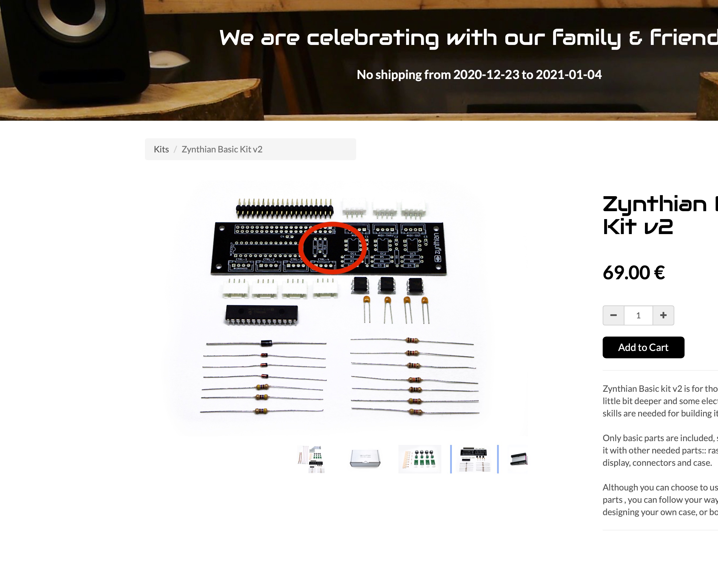
I noticed that the all in one board doesn’t have the SW1 in the store pic:
I assume its not been updated and if I buy the Basic Kit V2 it comes with the V2.1 all in one with the SW1 making an easy. S1-S4 addition.
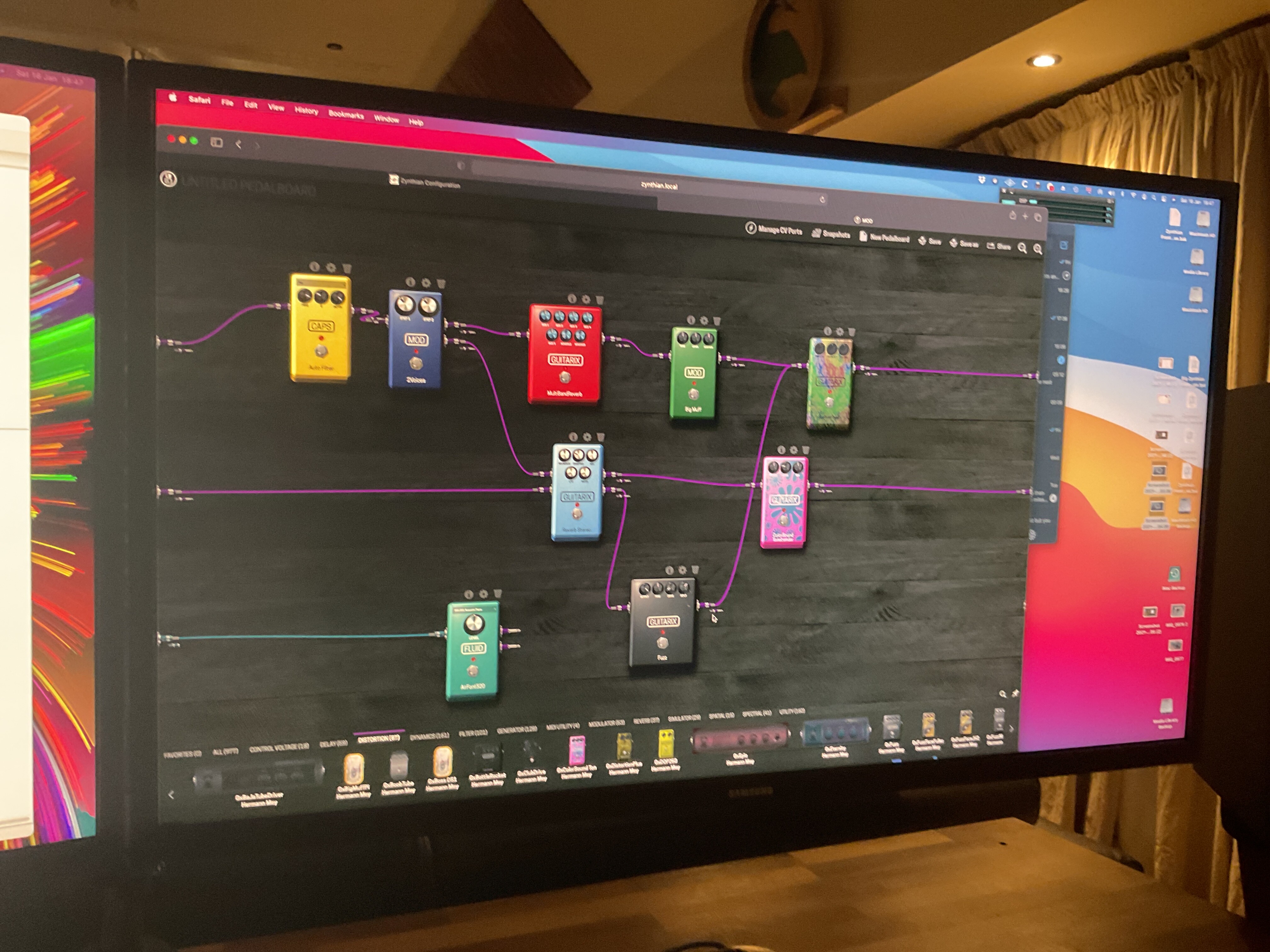
Yes the pedalboard layout doesn’t veer too much from the desktop except I’m adding a 5.1” screen. I have a Midi Maestro pedalboard to control my Aeros Looper pedal and a Mod Duo Pedal and I will probably integrate most of the control functionality in a dedicated page set for this…
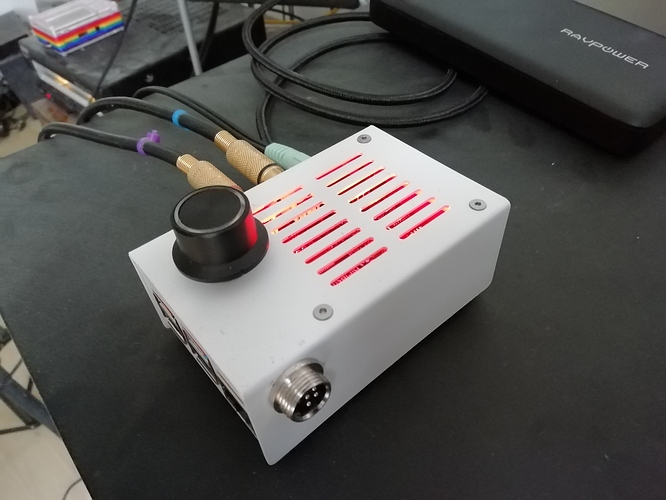
Balancing size vs usability means sometimes you will get a lot of air inside a project but I think this is nice for a v1. Its not too big & not too fiddly & small.
With foot based device weight is an excellent feature. It’s easy to move a guitar lead and have everything move which can lead to some fairly ballet like reaches to select the lead tone for the big solo…
Where are your connectors for audio mounting?
As to pedal boards there is my zynthian saga of long standing, admittedly a diferent meaning of pedal board but a lot of the observations might be relevant. [A pedalboard zynthian]
I have some Hammond M series pedals I have been considering converting into a Midi-Taurus alike. I’m probably unlikely to go with it until a bit later and would keep it as a basic midi controller.
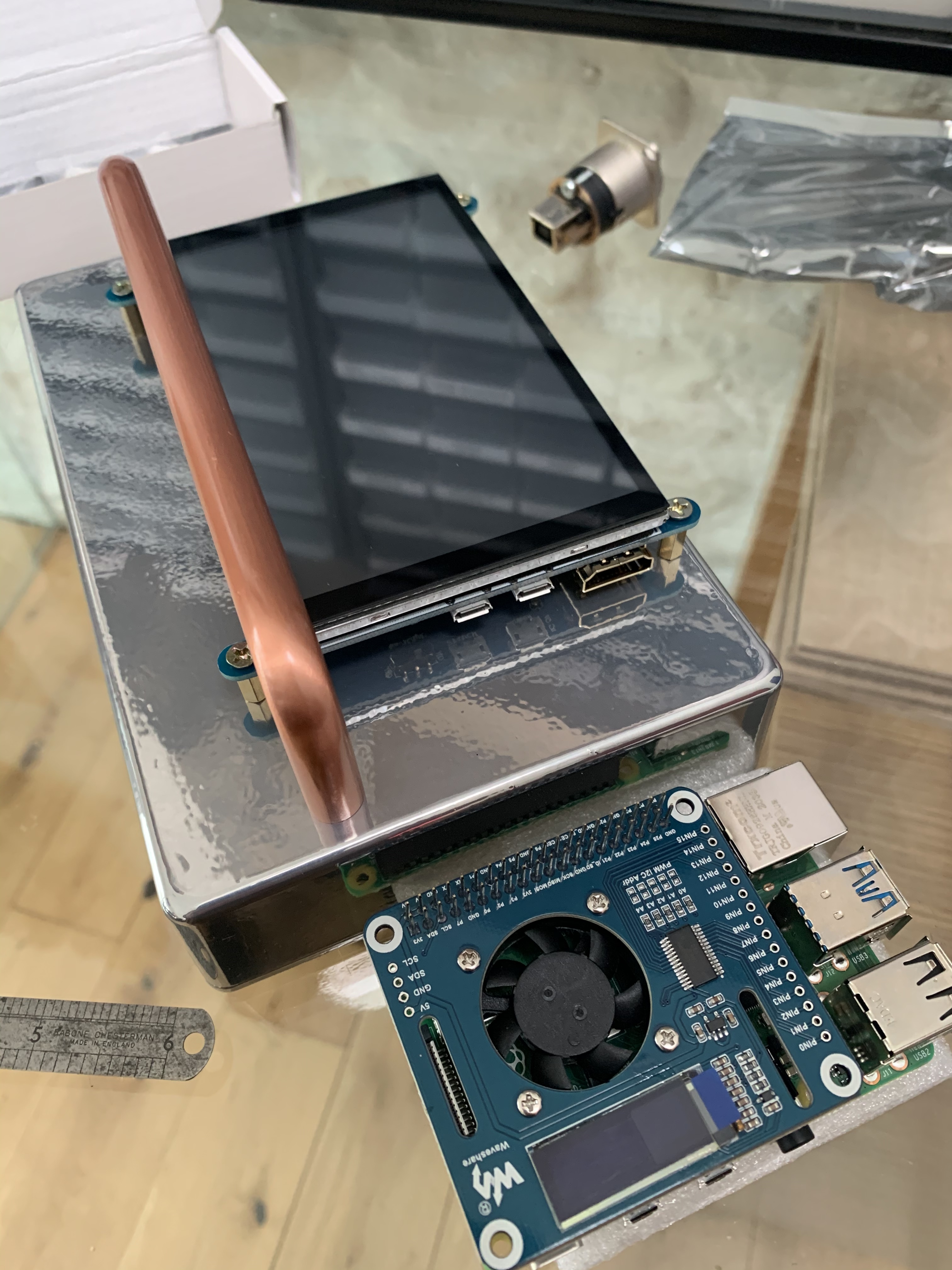
At the back. Additionally, 25-30mm venting on the left and right on the back sides. See how it goes with cooling but can add any off-the shelf Pi/Heatsink and fan cooler easily enough to to promote circulation.
The Pedal will be clamped to a single decker, single run DIY aluminium pedalboard using T-Slots and clamps. No Velcro. My welded steel Pedaltrain 2 is just too big and heavy and I can use the extra space in the flightcase for clothes and merch.
Yes, I have too many projects running at the same time and they all tend to interact with each other.
I’ve set this weekend aside to map 8 decent sounds to standardize on my zynths on 8 con current MIDI channels and use stage mode to switch between them. I really need to work on a couple of pieces that makes specific use of particular bits of kit and I take a lot of pleasure in finessing this sort of kit. Eradicating one connector or a particluar bit of kit is very satisfying and reducing the amount of clutter I take to stand ups is always a boon. I am always amused when people turn up with strange ‘special’ leads and grubby wall wart power supplies often in plastic carrier bags along side their pristine PRS in a case that cost more than my 12 string
I would check specifically with @jofemodo (Just private message him) as I’m probably more on the piratical end of the zynthian spectrum, he seems a decent cove ( for a european … sniff ) and will make sure you get what you need.
There has been a little discussion but more from the perspective of LED status display ( Jack Xruns, MIDI note that sort of thing …) .
We have tenxded to concentrate on info in… There is a flying fader set up for the Motor 61 which does it thou’ MIDI so I would expect that that would probably be the simplest implementation. So I press Zynth soft Switch 2 —> Zynthian as a webconf config. Then if we declare a set of MIDI status messages these could be re-interpreted as LED’s on and OFF but I’ve got a bit of an obsession with Zynth encoder and switch functionality over MIDI for my pedalboard control panel which I would love to do purely as USB MIDI at the moment…
That would allow passing this sort of stuff across networks of zynths in a sensible sort of way, but there is a certain amount of definition of controller & controlled devices to make that sort of thing work without getting your coding fingers dirty at the moment.
It’s also something I consider essential for the switches on the Pedal board. As a which patch is selected sort of thing at the very least.
And I begin! Ruggedised stomp box in a Hammond case is a go-ahead. Sadly the shipping costs for 4 x Encoder boards and 1 x All-in-One were a bit prohibitive as the order was 45EUR for just 5x PCBs so I’m using the Gerbers in the Git Repo to make my own, piggybacked onto a batch of boards for some stomp boxes, it costs peanuts this way as its tiled into unused space.
Still wondering about fitting LED rings and sorting out latching lighting later, these things can be mechanically a pig to retrofit.
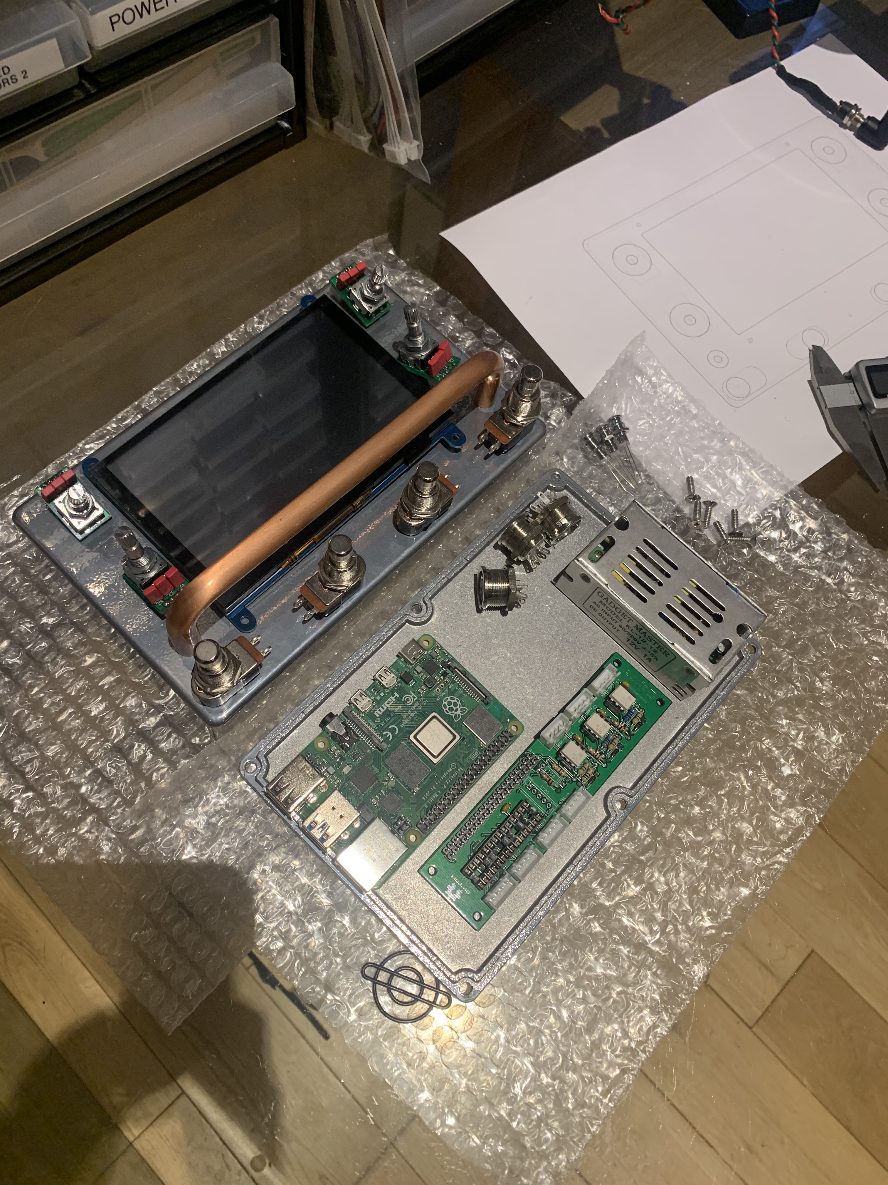
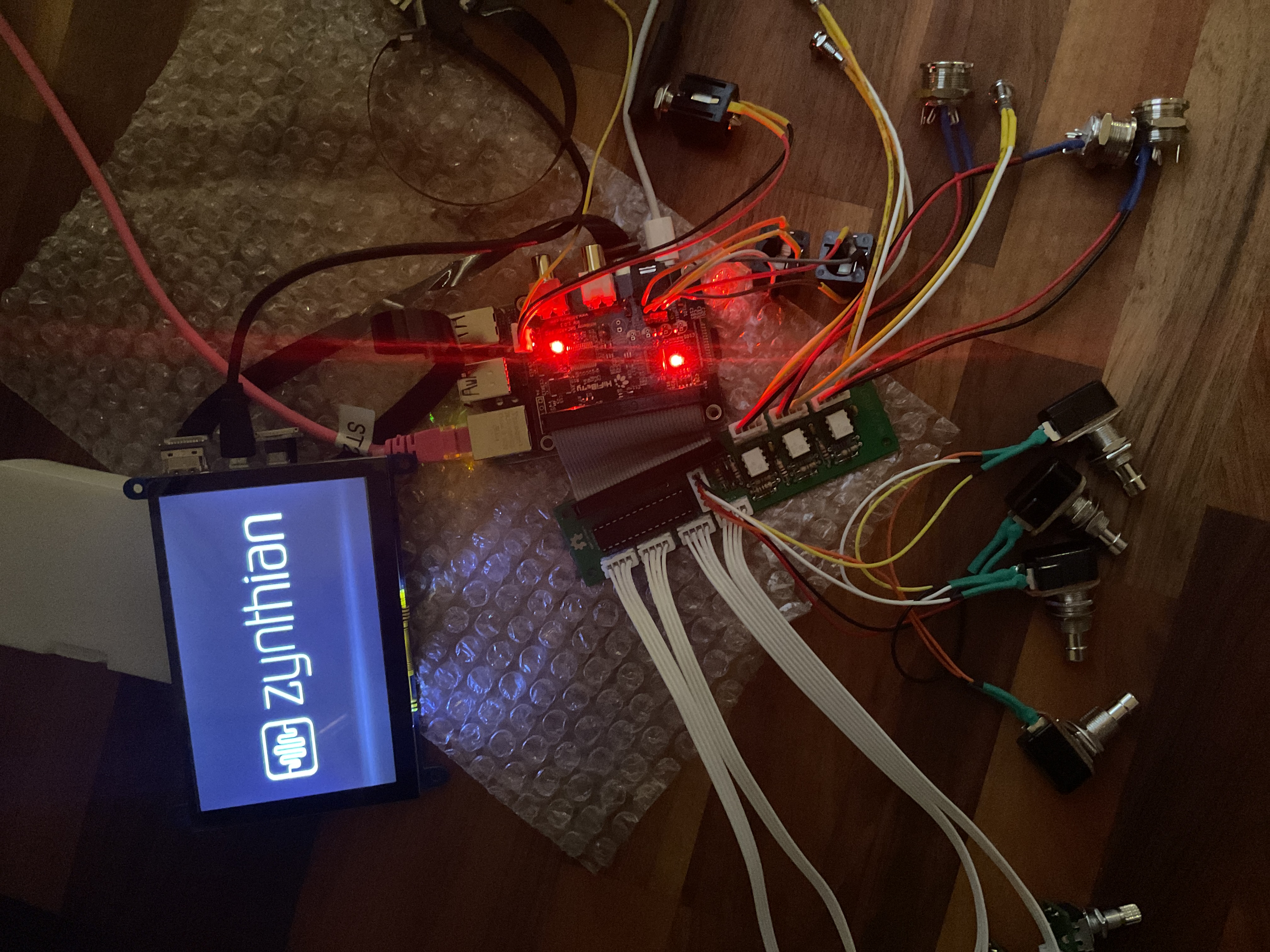
I’m still waiting on a few parts but it looks like I’m going to be able to fit everything inside a Hammond 1590DD case. I’d like to use a PWM controlled Pi Hat for cooling onstage/live but it may just be too much height for the DAC hat and the Fan Hat. Can cheat by putting a 3D printed shim to raise the top case by a few mm, but I’d rather not.
Out of IN5819s (which is always the way). Drowning in IN4001s.
(Ignore the 12V PSU, I’m going to juice it externally from my 9V pedalboard PSU and will use a buck converter internally to produce 5V/5A between the Pi and screen) but its the same frame size as the PSU.
All working fine and dandy, the midi LEDs are a little dim (or maybe I am being blinded my the DAC LEDs, either way , MOD-UI is up and running) Audio and Midi Test works; encoders and buttons all working now to check inputs.
This is so nice I think I might make a custom wooden enclosure and top plate for it rather than a brute force pedalboard. I made one for a DIY Midi Fighter based around a Teensy 3.1 a few years ago. Estimates show I can make it all ~35mm thick.


 … sniff ) and will make sure you get what you need.