Hi!
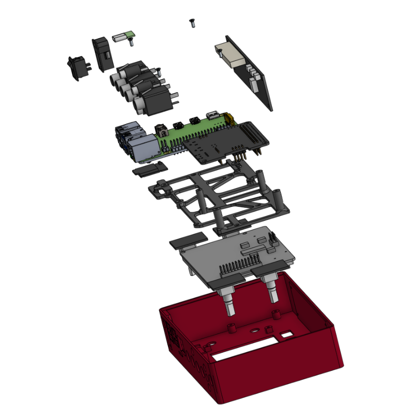
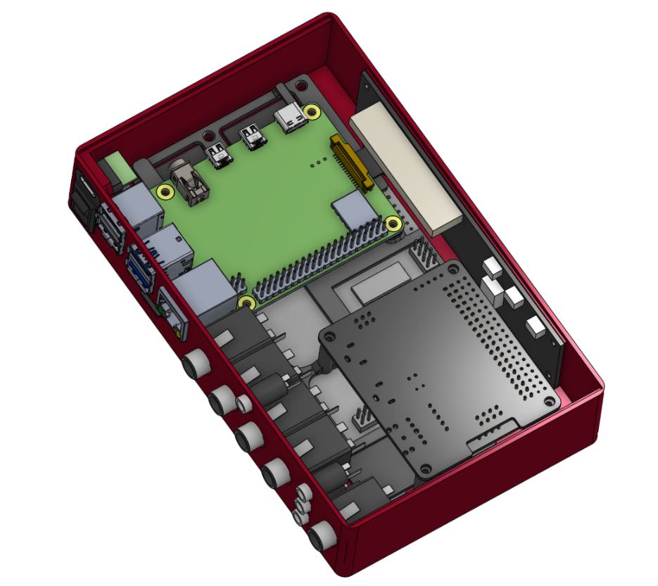
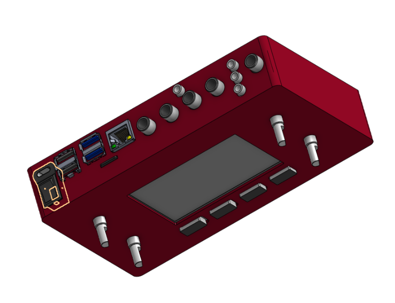
I’ve been building a super slim v4 without compromises (will share and post here when finished) and now i’m down to the cabling.
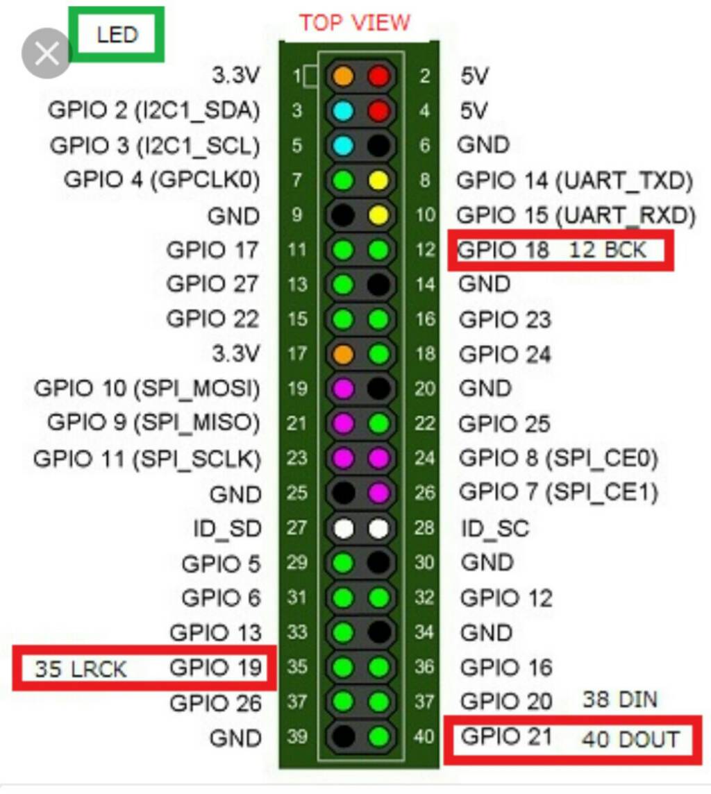
Turns out the 40 pin ribbon is not very flexible and takes up a whole lotta space, and from the diagram in the build page of the wiki i figured i might be able to use only a 26 pin ribbon if everything is using uart/i2c/i2s/spi.
Is there a pinout of what pins are used and which are not in the v4 kit? also wich ones are needed for each module?
Thanks for the breakdown, but this is also something that’s interesting, as running only the needed cables for each part would be nicer than having that ribbon everywhere
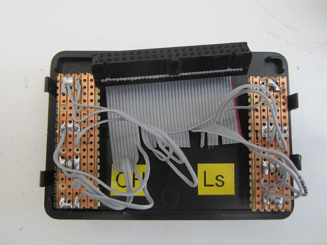
I’ve found you can be much more creative if you tear out the individual cores from a ribbon connector and cut the ones you don’t use. I tend to use the webconf to shunt pins into specific bunches. I find it much simpler to buy pre made 40 pin leads and cutthem down than try to make the 40 pin idc connectors in such setups as the inevitable movement can work pins into the dreaded intermittent state which are a real pain to locate especially in these situations.
Sadly the number of cores and size of the conductors in modern ribbins is considerably less than it used to be which means it all gets rather fiddly. But I’ve squeezed 40 pin connectors with ribbons and encoders into Hifiberry plastic boxes and it all seems to hang together. They’ve been on stage without mishap
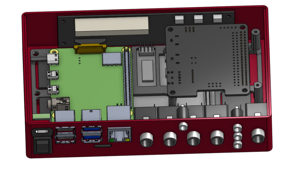
Hi @Pastitas, have you tried to flip and rotate 90º the soundcard? Perhaps you could align the row-pin connectors so you don’t need to fold the ribbon …
Flipping it is the real problem, maybe i can fit it, it’s definitely an option but the ribbon needs twisting anyway since the screen’s pin 1 is on the opposite side
one approach that has worked before is “de-ribboning” the cable after the connector is made, wich helps with the problem of twisting
As stated above, splitting the ribbon cable then removing unrequired wires gives far more flexibility. Individual cores are pretty lightweight and flexible. It is the binding into a ribbon that gives it the stiffness. Using multicoloured ribbon cable helps identify conductors when splitting out like this.
OK! I see … and rotating the display 180ª is not an option because the push buttons would lay on the upper side… or would you accept this?
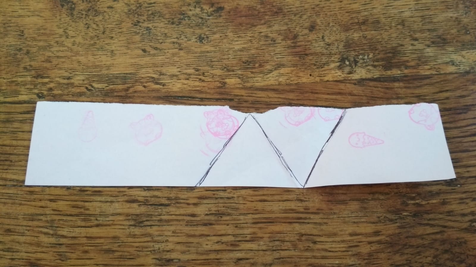
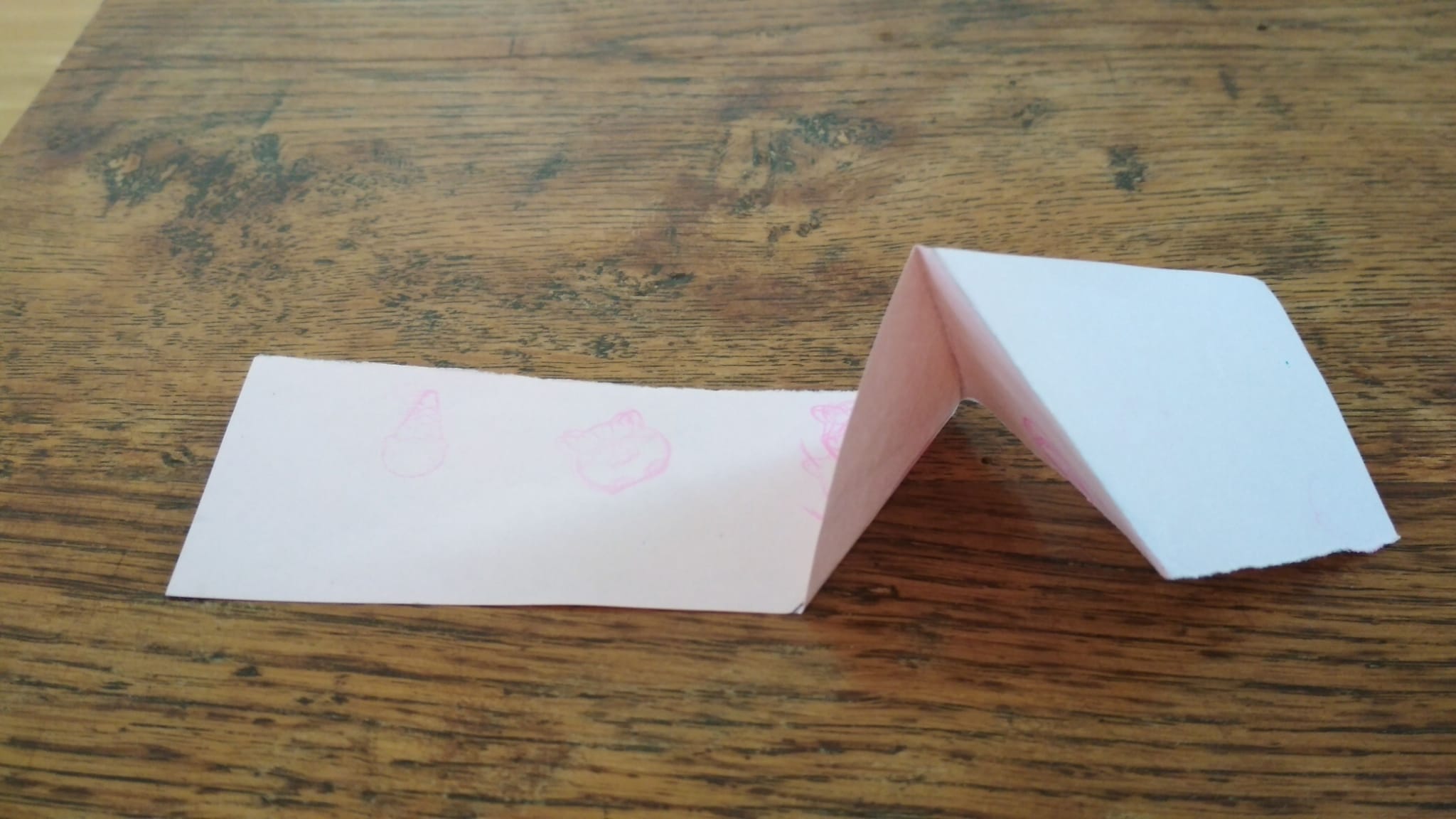
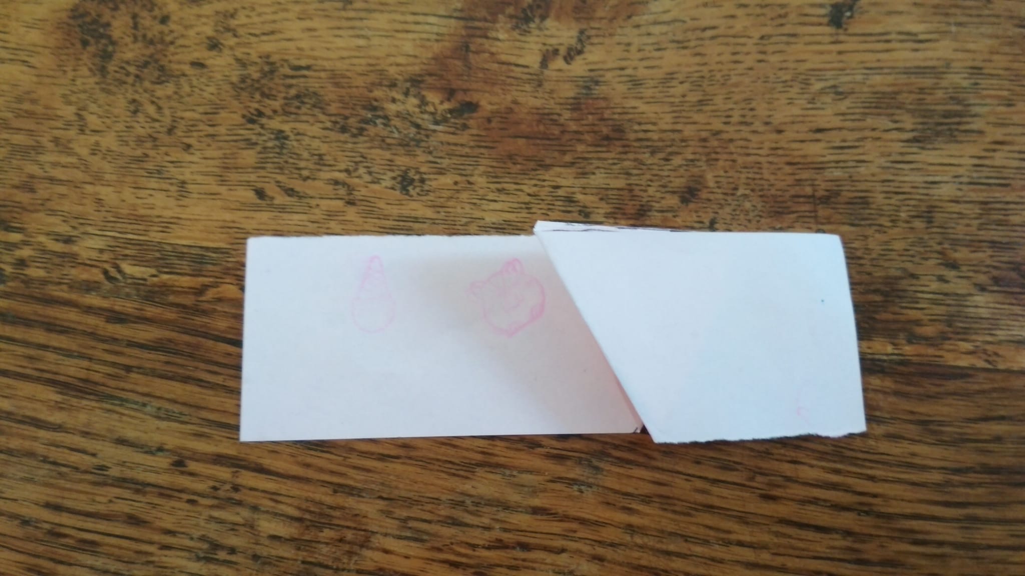
Anyway, if possible, i think you would get an easier path for the ribbon by flipping & rotating the soundcard. Flipping the ribbon is not so difficult. You can do it with 3 folds like that:
Yeah, that’s what i was thinking of doing, but how do you exactly go about this? dupont connectors and that’s it? maybe some pictures could clarify as i don’t think i’m understanding you
correctly
If you don’t intend to use the zynaptik extensions and only need the MIDI circuitry, then you could consider connecting only the needed pins with dupont wires:
BTW, why not to plug the soundcard on top of the RBPi? The heatsink? You could conduct the heat using a L- plate and place vertically the heatsink+fan, flowing fresh air from the outer space …