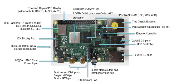
What do people reckon to this? I can’t find a definitive statement on the existence of a polyfuse on a Pi4B (I was looking for a photo for this post) Mind you others may know better…
I don’t see anything that looks like a polyfuse on the 4B, and do not see any reference to it on the schematic. I am thinking that perhaps the USB-C input voltage chip provides current limiting that would have previously handled by the polyfuse.
Might have to consider beefing up the supply cables.
I’m letting the pedal board have a rest just in case. I tend to run everything on pretty much all the time as a kind of unmanaged soak tests on multiple zynth’s which makes for some interesting reactions with false triggers on the pedalboard which adding some caps seems to have cured…
Well that sounds conclusive, No polyfuse on the Pi4.
Remind me again about the pedalboard project… Is this the Arduino style thing we are both working in parallel?
Yep, it’s rather an Epic… The PSU mechanism has been receiving a fair bit of attention recently . . . With a buck converter added to allow a little more control in this area. . .
The projectssitself has tended to overflow several threads, Zynaptik’s
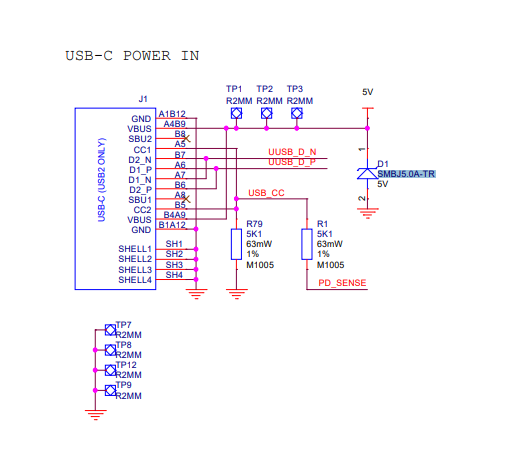
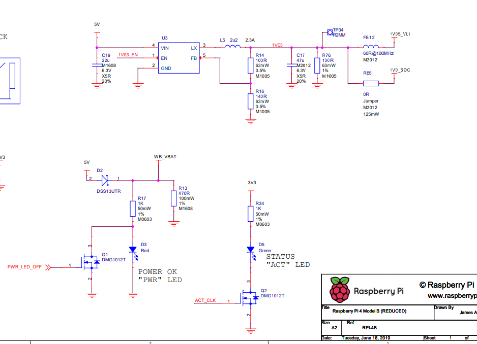
The Raspberry Pi 4 circuit schematic shows no fuse. There is a clamping zener diode and some power conditioning with inductors, etc. around the chips.
There is a note on the schamatic that @wyleu may find interesting: NOTE RUN IS 3V3, GLOBAL_EN IS 5V - I know he was looking at these features a while ago.
I use the global_EN as a reset from a front panel switch but I just short it to ground.
The second touch screen doesn’t have the lack of reset problem the first one has …
But I will probably beef up the cables in the PSU area.
The zener is interesting as I’ve strapped a 5.6V zener across the supply lines just to protect things in general…
While we’re talking about rpi4 powering, did anybody try to power the pi by Soldering wires on TP1 and TP12.
I plan to use in my New built a LiPo pack and a strong (3A given) adjustable stepdown converter.
I think that by doing so, I won’t bypass the raspberry pi4 power input protection system.
I’ve done it on the Pedalboard to TP1. In fact from looking at the circuit you are probably better off coming in via the GPIO connector as there is no polyfuse that was included if you did the TP1 trick.
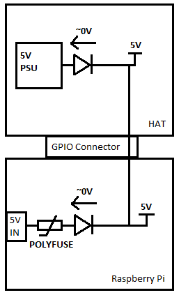
Thanks, I will consider powering the PI through header pins but as I read this (from official raspberry foundation Github’s account) and especially the note at the end I always thought some additionnal protection circuit is needed:
And, eg, when you start a new raspberry pi hat project with KiCad, the circuit above is already there in the template. And it is on the rpbi 2 board too.
So right now, I’m a bit confused. I don’t want to burn my new pi4
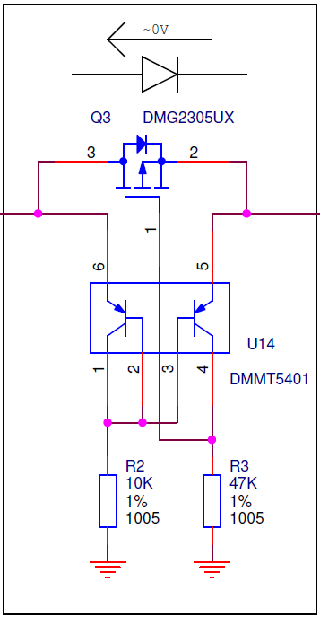
@le51, I built the epdf hat (Encoder, Power, Display, Fan) with the above referenced template, and ran into power issues with not enough current to run the “f” Fan portion of the epdf. The workaround was to jumper past this, true fix would probably be a large ish cap on the 5v output, larger traces than were selected by default, and a bigger mosfet in for Q3. The Pi was reporting voltage/current dips when turning on the fan, and I was using a 3A supply with spade connectors to the hat.
Hi, yeah I’ve Seen (and also followed carefully in an another thread, but it was some Time ago wasn’t it ?) your hardware developpement.
My question is : are these “protection” circuits necessary (Q3 and U14 above) as they are not present in the rpi3 and rpi4 schematics after the USB power in plug ?
I’ve Seen some threads on the raspberry forum where tinkerers are powering the pi with stepdown converter from Aliexpress through the gpio pins without this.
I read an article on this and people’s responses. Removing the power input filter is likely to cause issues with noise and stability. There were also comments about whether this (or other actions) disable or undermine the under-voltage detection circuit which of course means it just masks the problem which is worse. (There is a way to disable notification by configuration but it is there for a reason.) This piqued my interest for a few minutes but the inner engineer fought his way out of the easily impressed social media consumer to say, “No! Don’t do it!!!”.
For about two weeks, I’ve been powering the pedal board pi from a buck converter with a 100 microfarad cap strapped across it and a 5.6v zener fed to tp1 on the pi board using speaker cable… Seems far less prone to lightning and I can tweak the voltage as well and provide seperate power for the touchscreen.


 ,
,