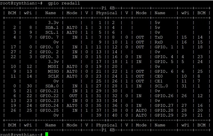
With the pins set as I wrote above the result is this:
With gpio readall the 4 buttons of the encoders work, but when you turn them nothing happens …
There is only a small window within each detent when the values change. The encoders are two switches which open and close on each detent so to detect a change requires moving the encoder partway through a detent. It isn’t that easy to test, hence why @wyleu suggests testing the pins with the switches.
Thanks Riban…
now I try…
Maybe I understand … I can try any pin with only the two wires of the encoder switch … and if a pin is 0 on gpio readall?
A gpio in the zynthian world is configured as a pulled up input. This means that it will read the value high unless its actually set low by an electrical connection to OV. So the Gpio pin reacts when it’s connected to OV. This is what happens when you press the encoder switch and as its nothing more or less than a switch it will show 0 in a gpio readall call until you let go when the pull up resistor in the pi will sense the completely disconnected pin as a high value and show 1 in gpio readall.
This allows you to detect correct operation of the encoder switch and also it can be mapped in webconf to actually operate the encoder D switch function which will do things.
The story is the same for encoder D on its two pins on the encoder that are very briefly connected to 0v via the encoder mechanism to indicate which way the encoder is turning. It’s just as @riban says too short to register reliably.
Once you have identified that encoder switch you can rewire one of the encoder end pins to the switch line and see if you can get that new io pin to work as the switch.
Once you have done this you can rewire these two discovered pins as the two ends of the D encoder and check to see if you get rotation on the encoder. You won’t have switch operations but you will have a working encoder rotation.
From there you can select another i/o pin as the encoder switch and you should then have a completely working D encoder as long as you can find 3 i/o pins that will behave out of the several available.
Thanks for the very clear explanation.
The problem, looking at gpio readall, is that there aren’t enough high pins available. I attach my gpio readall …
After hitting my head until 11pm … I removed the sound card and restored the pins as they were before trying the card … I connect a Focusrite USB and everything works … but … knowing me it is not over … I’m thinking about the MPC23008 that I have in the drawer …
If you identify what pins the soundcard uses you will know what are left. If that is insufficient then you will need to expand the quantity of GPI. There are a few ways this has been done, mostly using some form of I2C expansion. Official Zynthian uses MPC I2C GPI expanders. Originally MPC23008 then later MPC23017 which has more GPI pins. There are also some examples of using a programmable MCU like the STM32 or Arduino to create an interface. These are less well supported but do currently work.
You could use your MPC23008 to add 8 pins and complement this with RPi header GPI. This should give you all the pins you require.
Thanks Riban, always clear and kind.
I am not a fool with electronics … I am a Radio Amateur and I have built many radio transmitters with whom I have talked to the world … but this topic of GPIOs is difficult for me … You have a link to be able to see a example? Once connected, do the new GPIOs have a different name? Do I see them with gpio readall? Are they selectable via web conf?
Thank you
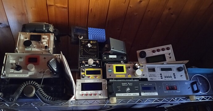
That is quite a collection of… junk? 
A GPI is a general purpose interface, a single port that may be asserted or cleared. This nomenclature is maybe less relevant in our modern, digital world. Many people now refer to these as GPIO which probably means general purpose input output. (I am old school so herbs to use the original GPI.)
Raspberry Pi presents many of the SoC interface pins on a 40pin header. Each pin may be used as a GPI or another, more specific function, e.g. I2C, serial, etc. The Linux kernel uses by the Debian distribution we use for Zynthian configures these pins based on boot-time configuration. Some are (indirectly) configurable from webconf whilst others are hard coded. I should think you should be able to find sufficient free pins bit of not then a GPI expander will help.
We use the I2C interface to connect an expander. MCP devices will use pin numbering from 100. They won’t appear in readall but there is a command to read the values. I’m not at a machine so can’t access it to check but @wyleu will be able to regale you with stories of the command and it’s usage. You will need this after connecting the MCP, configuring in webconf and rebooting.
The expander needs supply voltage and two I2C pins connected to operate. The first thing to do after connecting the hardware is to check the RPi sees the expander on its I2C bus using the command mentioned above that @wyleu will help you with.
Perfect.
I found a guide of Adafruit … but it talks about installing drivers … as soon as I know the command to see the expansion, I’ll see if it works …
Since you didn’t like my radio creations I’ll show you the rest (or part of the rest) … 
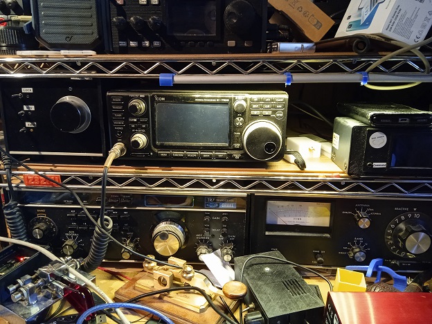
I love it. More organised than my like of old kit.
You don’t need extra drivers. Zynthian supports the devices. It just needs to be configured.
OK thanks.
Can I use a Custom configuration?
Once I know the expansion pins, I connect the encoders (I would also like to connect the new 4 buttons … even if I have not read what they are for …  )
)
Meanwhile I found this connection diagram … Then I’ll hear from Wyleu if the pullup resistors are needed or if you can set the door with his…

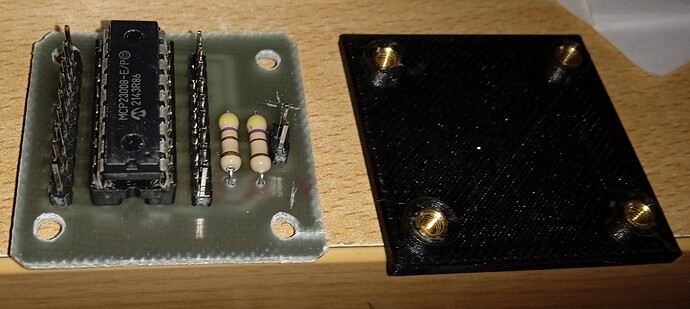
While I am waiting for Wyleu to understand how the Raspberry says that this interface exists, I milled the pcb and assembled the components … I would like to point out the wonderful serigraphs + and -
I love the fine calligraphy.
We plainly can’t wait for our friend so I fired up my laptop and checked the command. (I would have done it earlier but have been busy trying to renovate sash windows whilst suffering gastroenteritis.)
i2cdetect -y 1 should show you a grid of results that indicate the I2C devices detected on the bus. Mine looks like this:
 0  1  2  3  4  5  6  7  8  9  a  b  c  d  e  f
00:          -- -- -- -- -- -- -- -- -- -- -- -- --
10: -- -- -- -- -- -- -- -- -- -- -- -- -- -- -- --
20: 20 21 -- -- -- -- -- -- -- -- -- -- -- -- -- --
30: -- -- -- -- -- -- -- -- -- -- -- -- -- -- -- --
40: -- -- -- -- -- -- -- -- 48 -- UU -- -- UU -- --
50: -- -- -- -- -- -- -- -- -- -- -- -- -- -- -- --
60: 60 -- -- -- -- -- -- -- -- -- -- -- -- -- -- --
70: 70 -- -- -- -- -- -- --
You will see that I have devices with I2C addresses: 20, 21, 48, 60 & 70.
Run the command with your expander disconnected then connect it and see whether you get different results. We would hope to see the expander detected on its I2C address. The address is set on the MCP23008 buy setting A0…A3 on pins 3…5. These pins are not internally biased so you need to tie them to a supply, e.g. 0V. The I2C address is: 0 1 0 0 A2 A1 A0 so if you tie them all low it will have an address of 0x20. If you have nothing else connected then that should be free.
Many thanks Riban.
I immediately begin to try … unfortunately my Googleian English does not allow me to perfectly understand what you have written … but, doing some tests, maybe I understand
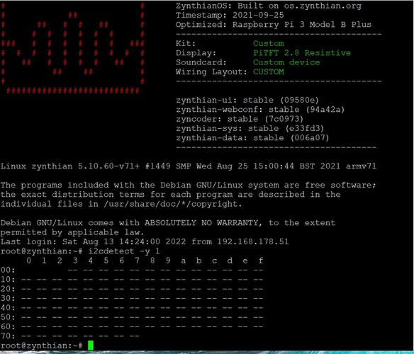
Unfortunately, both with the expander powered and not powered, the result is the same.
I ask you (provided that you are not suffering from gastroenteritis …), should the MCP be powered at 3.3V?
The two ports to connect it to are GPIO8 SDA1 and GPIO9 SCL1?
Always thanks
… or should I use GPIO30 SDA0 and GPIO31 SCL0?
Always thanks
SDA is connected to pin number 3 on the physical rbpi header (BCM 2}
SCL is connected to pin number 5 on the physical rbpi header (BCM 3)
Perfect Thanks le51
For Riban:
Another information for you … If I scan i2cdetect -y 1 with the expansion not powered, the scan is slow and does all the reading … if the expansion is powered, when I press ENTER it immediately appears all the scan (sorry for the weird explanation)

