Normal ![]()
Ok, thanks…But to see if it works … what should I do …?
If I give the command i2cdetect -l, it tells me to see only the bcm.
But above all, how do I know the number of the pin that I would like to use in the expansion in order to insert it in webconf
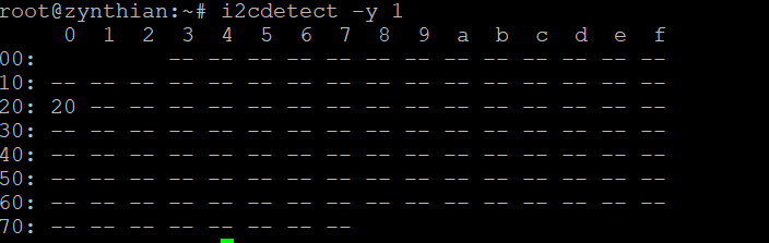
What’s the output of i2cdetect ?

Your port expander isn’t recognized .
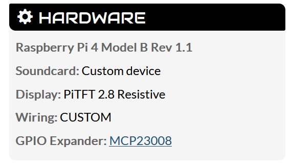
According to this
Mcp23008 has a reset pin that should be at high level
Ok le51. Thank you.
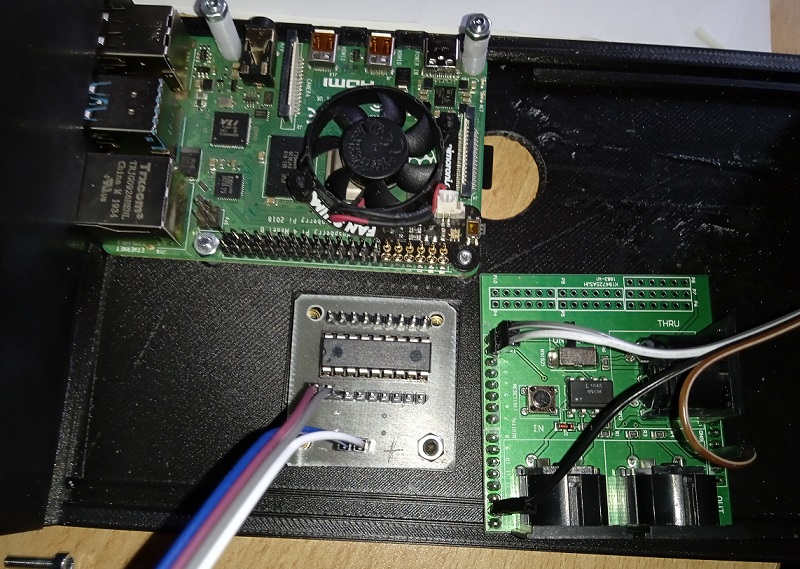
So compared to the scheme I had found there are two differences … in mine there are two resistors from scl and sda and + … but above all the MCP23008 is powered at 5V and not 3.3V.
I immediately do further tests. Thank you
I soldered a 100n smd capacitor, I eliminated the two resistors and I powered at 5V … something has changed … 
Now I have to understand what the GP0 to GP7 pins are called to be able to use them in webconf
If I can get the expander to work … I want to try to insert the midi shield
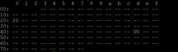
Yay! Well done! The RPi is now recognising your expander on I2C bus with address 0x20.
You need to connect the MCP interior pin to a spare RPi GPI and configure the address and interrupt in webconf.
The GPI pins will present as 100-107.
Damn my ignorance of GPIO …
Can you explain it better?
So, the GP0-GP7 ports of the interface become 100-107 … OK.
What does this mean? "You need to connect the MCP interior pin to a spare RPi GPI and configure the address"
Thanks Riban
Are these the settings to fix?

We want the communication for the Encoder D to travel over the 12c bus rather than the GPIO pins used by the other three encoders, which we have already configured.
The GPIO pins details we have already entered into the Hardware Configurations with the numbers we have already described for PIN A, PIN B & Switch.
The D Encoder will be connected to any 3 pins of the 8 available, entirely of your choice, on the MCP23008 . It’s up to you, choose wisely. ( I mostly do it to suit the wiring layout and try to aid rereading/debugging by keeping it logical but even the choice of switch first or pins first is pretty arbitrary). So it needs configuring so the zynthian software ( Zyncoder) know where to look for a working encoder. The trick is local knowledge. You add 100 to the ID, but do remember these are not the pins on the chip they are the names of the pin from the datasheet specification.
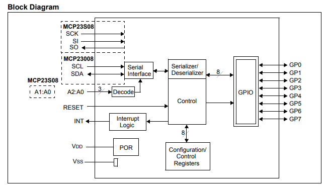
So this chip talks on one side to the zynth and on the other side the 0008 GP pins GP0 to GP7. Now this chip has three different packages, two of which you need a machine to solder repeatably. So you are using the simple 18 pin package…
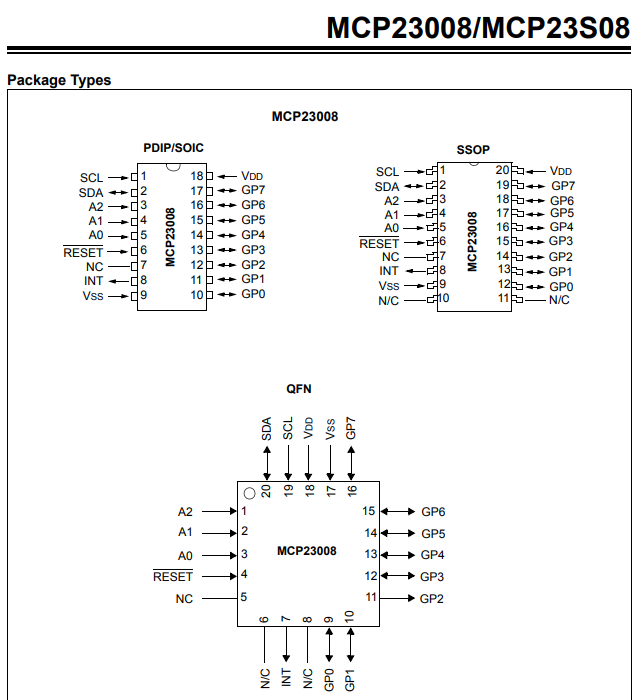
so you are dealing with IC chip pins 10 to 17.
We know that the chip can be seen by the zynthian software because 20 has cropped up in the ic2dump -y 1 command line utility. Which is great because all we need now do is solder the 3 gpio pins on the encdoer D and then see if you can find them as we did with the GPIO pins. so you are adding a n entry into your switch setting with something like 100 ( GP0 ) to 107 (GP07).
But there is important issue to consider. To get to read the Encoder D we need to constantly examine it to see if it changes… Now actually that’s a lot of computer effort as the operating system can spend all it’s time reading these controls ( imagine 64 of them for example), and we’d rather that effort went into making lousy church bell recordings play…
So it would be so much better if the MSP23008 actually said I’ve just seen a value change! and the operating system can then go and grab the new value and get back to being a piano or whatever.
This is called an Interrupt because, in the polite world of computing, the device is interuppting the host machine. But it needs a separate wire to communicate this intent.
Basically It changes the value on the INT pin to tell the Zynthian there’s a new value to grab. But this wire goes to a old fashioned Raspberry PI GPIO and obviously the zynthian needs to know which pin of the many available have you chosen.
This should all work. We can read data directly from the i2c bus but one of the great joys of using standards is you can assume much functionality one a device has identified itself (0x20 ) to the operating system.
So thats what the
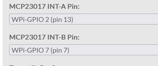
Shows and configures. The modern zynthian allows two 16 GP pin chips ( The MCP23017) so it needs two interrupts to signal the two different chips activities.
So in summary.
1/ You tell the Interrupt pins where the GPIO for the interrupt pin is connected. in one of ettings. If you can chose an existing default. It males your rig closer to the zynth kit.
2/ Choose and solder up your encoder pins
3/ Configure the 100 + GPN number for encoder D as was done with the other three encoders.
Welcome back Wyleu and … thanks for your patience … your patience (Wyleu, Riban and le51). I know that you are on a tropical beach and you are worried about the space that Lanfranco steals from the server and therefore you have answered my HELP !!!
Now I have connected the wires of the encoder D to the terminals 100,101e102 of the expander and, in webconf I have corrected with the new numbers … but it gives me ERROR at startup …

This is the new result of ic2dump -y 1.
has something changed…
I’d do just the Switch pin initially and check the GPIO wiring for that Interrupt pin. I can’t remember if i2cdetect actually involves any interrupt connection, I suspect not.
You need to go back to the last working version and small steps.
I do it immediately …
What I do not understand (my school English is about 40 years ago) is the speech of the interrupts … Does this connection happen physically with two wires or via software?
Yeaaaa! The D switch connected to port 100 WORKS !!! Thanks to you I am on the right path …
Does this connection happen physically with two wires or via software?.
IT’s very much a wire. The pin on the MCP23008 should be connected to the specfic GPIO pin…
My, possibly more modern test branch, has an option to define the i2c port that the chip is connected to.
Unfortunately I don’t understand this thing … (damn me who don’t cultivate English …) But I connected the 4 encoders switches to pins 100,101 and 102 … I updated them on webconf and they work … . but … I navigate perfectly but when I select a sinth, everything crashes and I no longer navigate …
Command line
journalctl -f
to see what happened when it crashed.
When it crashes I lose the connection with Putty … maybe it is better that I disconnect all the encoders and start over … anyway we did a step forward …
OK, with the pins of the encoders set to 0 and only the pins of the connected switches, everything works … obviously with the touchscreen … so it’s a conflict …
Make sure you aren’t shorting the wrong GPIO pin to ground via the encoder. IT could be nothing more or less than a short circuit via the encoder.
OK, with the pins of the encoders set to 0 and only the pins of the connected switches, everything works … obviously with the touchscreen … so it’s a conflict …
now the SD card is crazy … I am using cheap SD cards and then replace it with a quality one when everything is working … I keep you updated and I hope to be able to use it as soon as possible 
Interupt: You should connect pin 8 (INT) of the MCP23008 to a spare RPi GPI then configure the “MCP23017 INT-A Pin” setting in webconf to that GPI.
Many thanks Riban