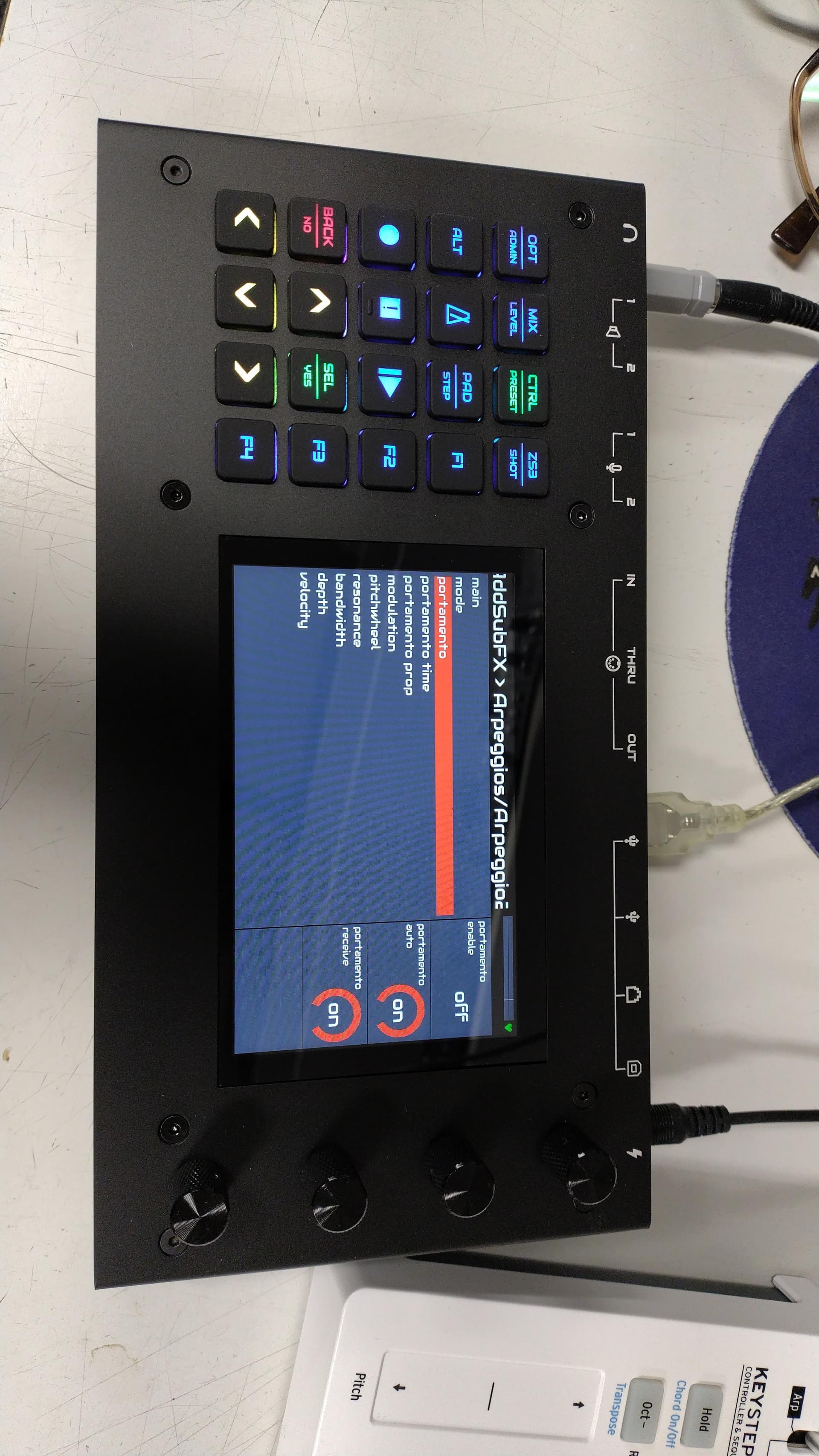
The knobs acting like a keyboard (encoder), so if you program it on rotating left like Tempo - and rotating right like Tempo + every time you turn left (infinitely), the knob pass to zynthian a minus sequence (like if you Hit minus key on your keyboard), so if you turn clockwise the knob it can pass + (like hitting + simbol on your keyboard).
Another function is that every knob can also be pressed (like rotary encoder) so on every knob you can program 3 different keys of keyboard, for me this function is very useful to set “Tempo” pressing the knob, opening screen Tempo, and when I turn left (anticlockwise) the “Tempo 120bpm value” decrease 1 time, per rotation, and when I turn it right (clockwise) it increase 1 time per rotation.
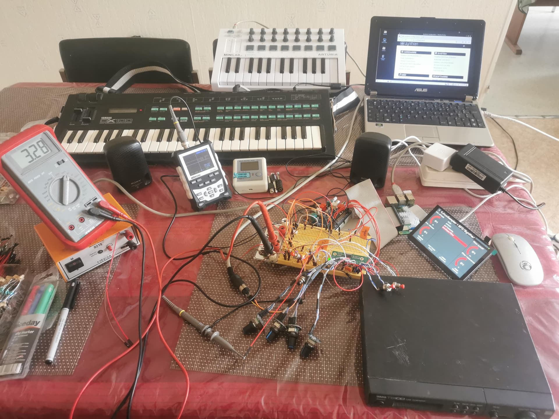
This encoder is very useful, in combination with Zynthian, but I cannot find in Zynthian Binds UI the option to increase or decrease volume…
It’s not a problem because I have a touchscreen display, and I have mapped the volume control also on my midi keyboard…
I found another good thing online (Aliexpress), the stickers for my 15+3 macro keyboard, i will post a photograph.
Ps: you can also program by pressing knob the “Tempo Tap…”
Pps: the macrokey picture posted below, was powered off, …but when turned on the led are on, and it’s fantastic…to see all the leds on (like in my first picture).
Ppps: this chinese “macrokey” works like the best keyboard (better than Logitech, Trust, or every other brand). Its very useful also to play games…you can use in portrait or landscape mode (because keycaps are exchangeable, and you can set it in 4 different positions, up down, left, right)…