5 volts 
That seems odd. A common scale is 1V per octave and MIDI 0-127 covers over 10 octaves. I think (from long distant memory) that the voltage range for such scammers is usually 0-10V.
Really? I always thought Control Voltage standards for Eurorack are bipolar signals that range from -2.5V to +2.5V. I could be wrong though.
Eurorack uses +/-10V for signals, but many digital modules only have +/-5V or 0-5V.
There are attenuverter modules with DC offset that help to get the voltage into the needed range for the in/output you desire.
1 Like
Indeed there are modules that only require a lower range of voltage but I am specifically referring to note range which for the Moog like range expects approx 10V range across the full MIDI note range. We can use a smaller voltage range but I would expect that to be represented by a smaller MIDI now range, e.g. 0V - 5V may represent a MIDI note range of 60, not 128.
AFAIK, there is not a truly fixed standard for CV signals on eurorack. Wikipedia says:
Eurorack defines a common power supply and power connector: a 10- or 16-pin ribbon cable supplying a dual rail 12v DC power supply. Power connectors can also include a 5V DC power supply, and CV and Gate buses.
Audio and control signals are exchanged between modules via 3.5mm mono jack cables. The electrical characteristics of signals are split into three loosely defined categories:
- Audio signals are typically a maximum of 10V peak-to-peak (i.e. between -5V and +5V)
- Control voltages can either be unipolar or bipolar. >Bipolar control voltages are typically 5V peak-to-peak (i.e. from -2.5V to +2.5V), unipolar voltages between 0V and 8V. The V/Octave scale is used for pitch information
- Trigger, Gate or Clock signals are digital 0V to 5V pulses typically used for timing and event signalling.
As I don’t feel too comfortable with “current pumps” and this kind of stuff for getting a bipolar circuit from a unipolar power supply (I must learn more about it!) and I didn’t want to make too complex the initial Zynface design, i thought that using 0-5V unipolar was not so bad. My SQ1 can be easily configured to output 0-5V, for instance.
Anyway, i would like to add a better CV input/output interface in a next iteration. Until then, as @STM says, you can use an “attenuverter”.
Regards,
1 Like
Aha! I am ahead of the curve then…
I have one of these
https://mutable-instruments.net/modules/shades/
That should fix everything up for me! Great news… As you were!
hi @jofemodo,
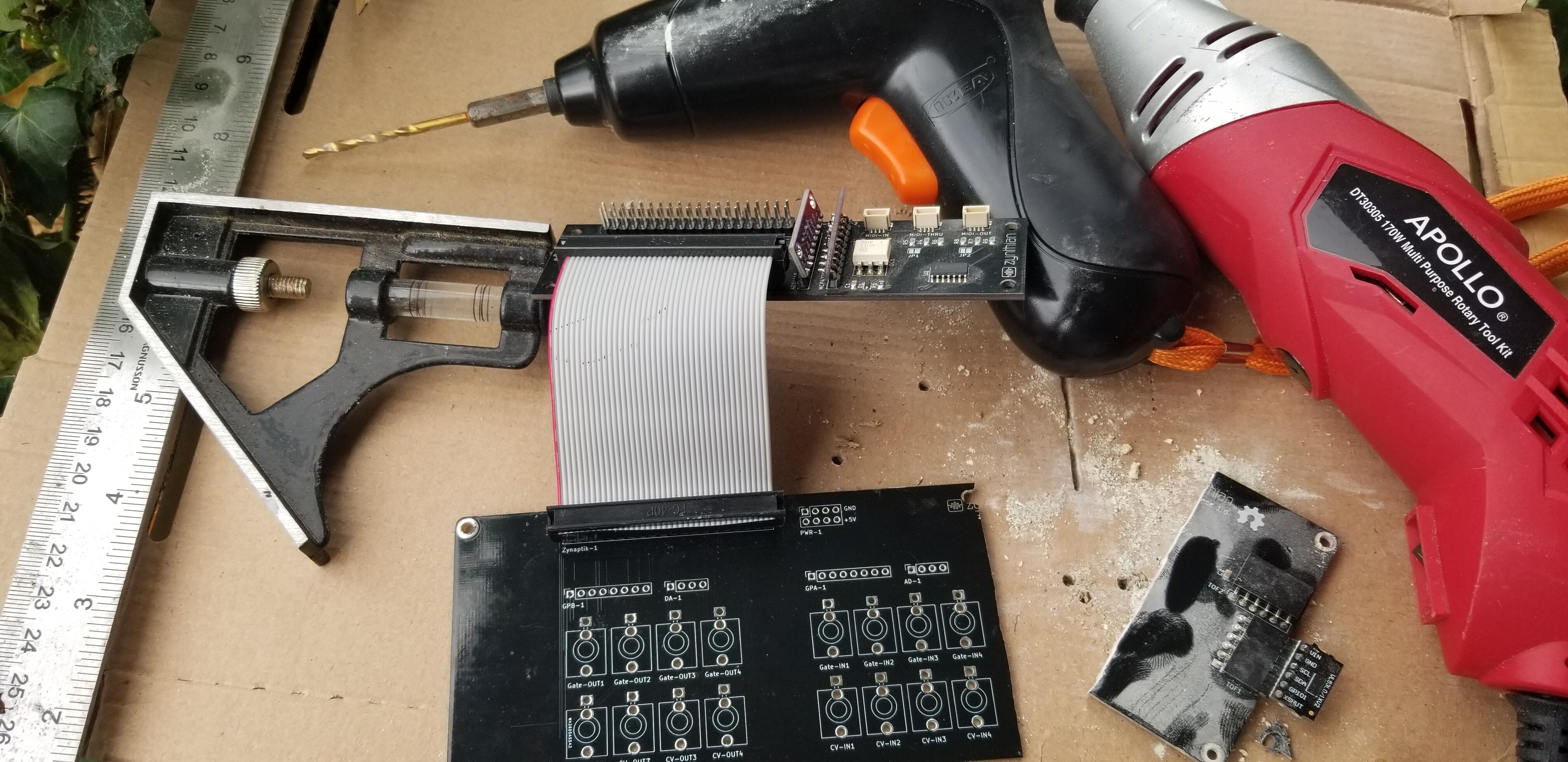
the front panel is finished
in principle, I put everything together
the required modules have been added from the cvgate branch, but I don’t really understand how it should work.
cv in works, but gate in / out and cv out do not
is there any tutorial I could use to make it work?
thx
6 Likes
Love your setup… I have been getting into modular recently, but it looks like you have been enjoying for some time!
1 Like
Hi @tsab !
Please, change to testing branch on all repositories and update. Perhaps you could burn the latest stable release too 
I have to update the wiki documentation, but webconf interface should be clear enough about how it works.
Regards,
I’m sorry, but I still don’t understand how it works … what triggers that channel? even if I set it up, nothing happens.
do I need to set something up or use a plugin? could you submit your settings?
thanks!
1 Like
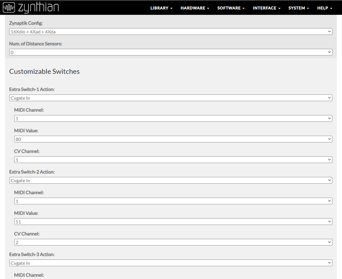
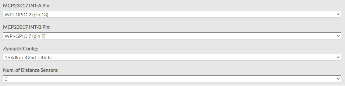
When you select “CVGate-In” for a Zynaptik switch, you pair the switch when one of the 4 analog inputs (CV channel, from 1 to 4). Also, you have to select a MIDI-chan and a velocity value (MIDI-value).
Once the CVGate-In is configured, you should see Note-on/off events on the selected channel, with the selected velocity, following the Gate triggers and CV voltage (note number). I tested with my Korg SQ-1 and it works fine.
CVGate-out is almost the same (no velocity value option), but reversed
Regards,
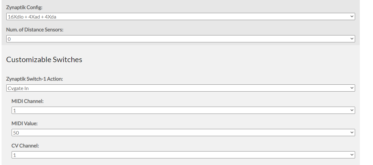
I just realized that my development environment has the analog connections reversed and current version on testing has too. I mean, webconf’s analog numbering is reversed, so when you select CV channel 1, you are selecting 4, and so on.
Let me fix it …
Regards,
That’s a  if ever I saw one
Press on the link in the icon if this makes no sense.
Ok, I totally butchered my board like this !!
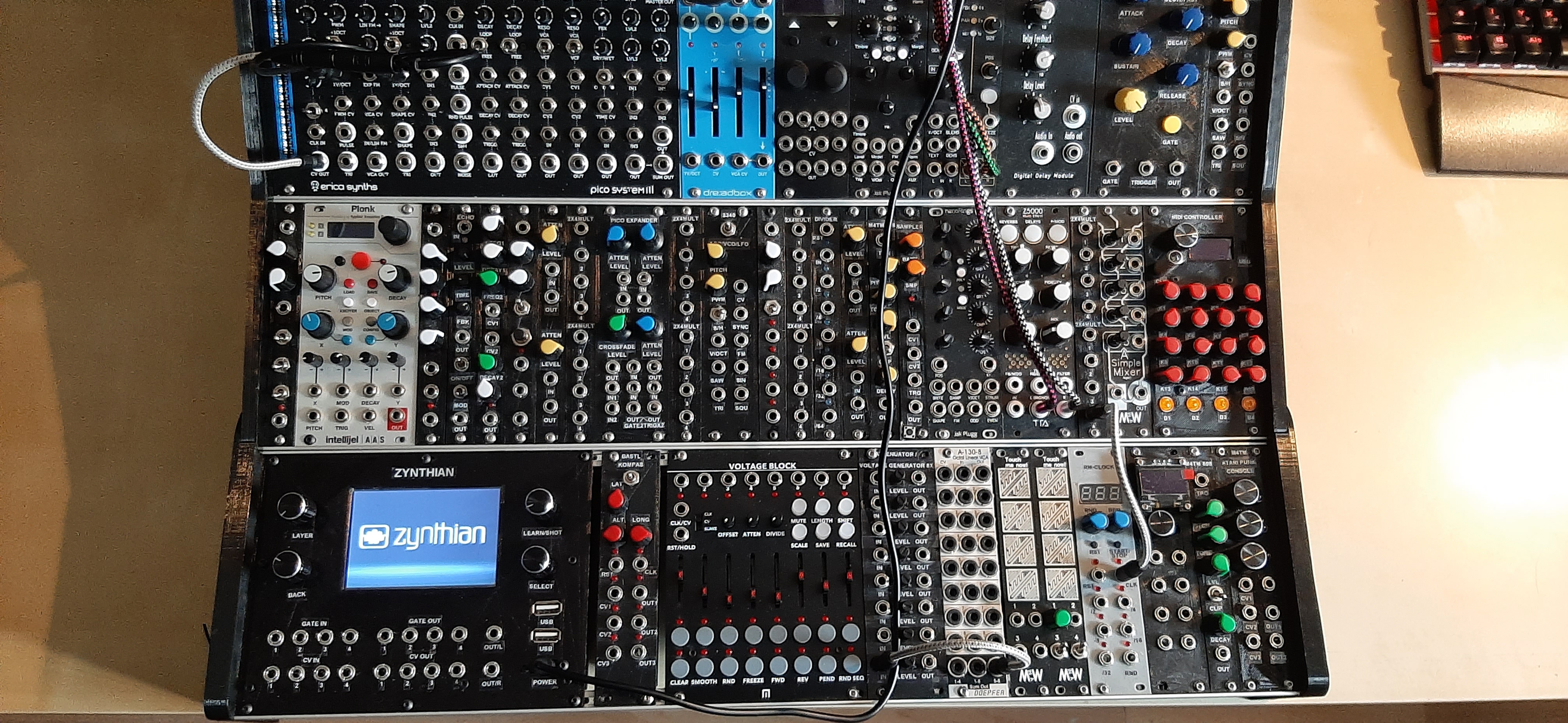
And the zynface now fits in my euro rack nicely even if the zynaptik is just hanging around out the back (see the picture)
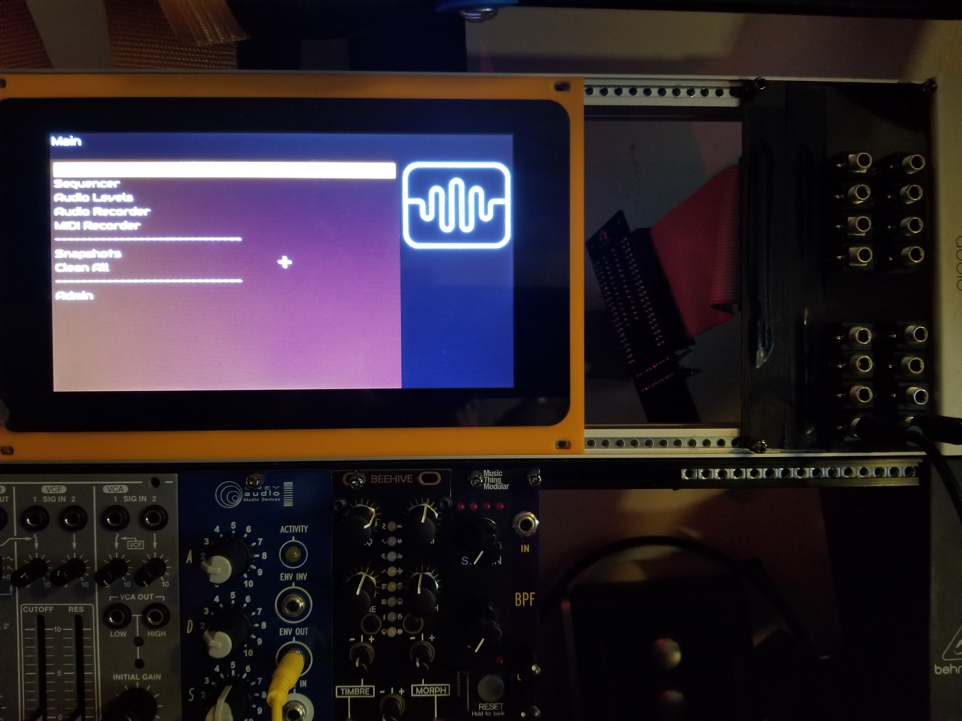
And the zynface now fits in my euro rack nicely
even if the zynaptik is just hanging around out the back (see the picture)
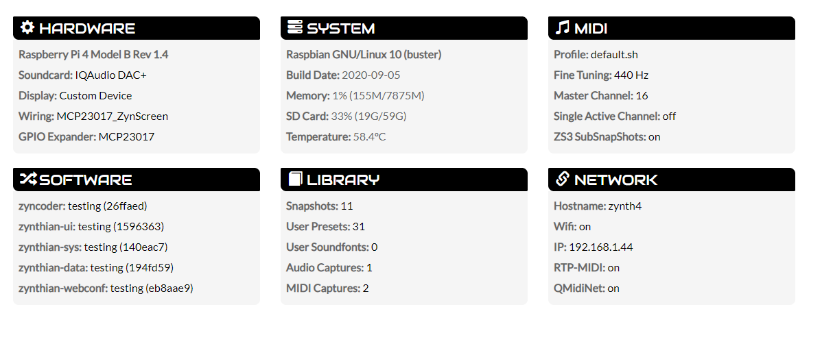
Now I am stuck… I am using a pi foundation 7" screen, so none of the settings below seem to be correct…
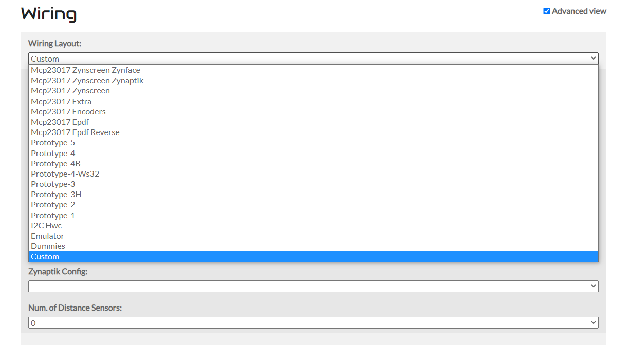
What should i set this screen to ?
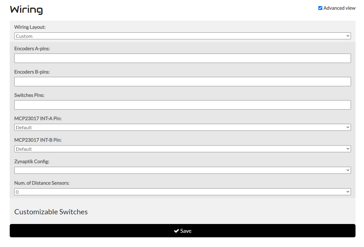
I have tried as follows, but when I do, my zynth wont boot / errors
I will try further to debug, but i wanted to check my settings were as they should be first
I got it working!!!
Some input docs.
Hi @jofemodo! I eventually found time to build my ZynFace today but am a bit stuck without a build guide. I guessed (with some reference to your drawing and videos) that the connectors all point out of the silkscreen side as well as the 3.5mm sockets and that is where I have soldered them. I also put the 90 degree connector pointing out of the board (over the silkscreen outline). I have soldered the DIL pins to the more populous, non-silk screen side of the VL53L0/1XV2 boards which I assume is correct so that the laser sensor points out when it is plugged in.
Assuming that is all correct, what way are the VL53L0/1XV2 boards plugged into the Tof1 & Tof2 sockets and what is pin 1 of the 40-way DIL header?