Anyways, Since Zynthian is typically running on a Broadcom Arm chip rather than STM32 I looked for the analogous info on Broadcom Timers, without finding anything - I think because Broadcom actually makes encoder chips as well they tend to swamp the search results.
I think this becomes more critical when the rotary encoder is being used for motor control as opposed to human interface and a person turning a knob.
And I’m going to drop the topic there. If any other intrepid souls want to pursue the topic on Broadcom timers, or Zynthian on STM32, or Zynthian on another CPU (RISC-V anyone?) May the Force Be With You…
The problem with Zynthian’s implementation is that it uses a GPI expander that raises an interrupt when an input changes state so noisy inputs have significant impact on the core.
We discussed using another interface like the STM32 and my first Zynthian did exactly that but at the time we were considering using development boards that required USB to upload firmware.
Since then I have developed a greater understanding of STM32 and now use them directly on riban modular PCBs. This allows the denouncing, filtering, processing, etc to be offloaded crib the main CPU / SoC.
Maybe it’s time to revisit the idea of using a microcontroller in place of the I2C GPI expanders for the next version of Zynthian?
Currently we have no issues with this. Encoders work flawlessly with MCP23017 + debouncing caps. Perhaps in a future version we would consider using a uC, but certainly not in the next version.
I have no personal POV about what’s the best solution for Zynthian (port expander vs dedicated MCU (*), but it’s good to know the direction the project will follow in the near future (note that the same questions goes for “display system”, “digital audio setup” and so on).
(*) except MCP23017 looks quiet expensive compared to STM32 chips and their capabilities. But for sure, it’s a radicaly different approach.
Hi @jofemodo . I have now created pull request for zyncoder repo for merging code for supporting MINI V2 hardware. I have also raised another pull request for merging webconfig changes to enable this settings. Please review and let me know if something need to be changed. Thanks !
It’s merged! The “MINI V2” is officially supported by the zynthian software (Oram branch).
Congratulations for your excellent work. I must say that i’m very happy of seeing how all this has going on. You followed the rabbit hole until the end and now we have a nice kit, very DIY and totally supported by the latest software.
I would like to add your designs to the zynthian repositories:
That is great !!! I am just flashing oram now to test it from scratch before writing final building instructions.
Definitely I will create a pull request for both to be added into zynthian-hw and zynthian-case. I just need to finalize few small details based on latest testing.
I am using github wiki for building instructions. Can I move this content to official zynthian wiki site if somebody would create a section for MINI and give me the access to create the same content ?
I learned a lot doing this - thanks to everyone contributing for such a great project !!!
Zynthian MINI V2 is now fully ready for people to build. Changes to oram that @jofemodo merged yesterday has been tested and they worked flawlessly for easy MINI V2 configuration.
Zynthian MINI wiki is updated with details what components are required, where to find them and how to assemble everything.
Zynthian MINI github main branch now include all design details for PCB in KiCad as well as for Case in FreCAD/Ondsel.
Now, I will focus on including this into official zynthian github as @jofemodo suggested yesterday.
Also I believe that it would easier and cheaper to create top and bottom cover using PCB design software simple by copying the PCB and then removing components and traces and creating a new footprint with just a silk screen for top labels and putting that on it. Producing such PCB is probably going to be cheaper than buying acrylic and cutting it on laser cutter .
FreeCAD is not easy to learn but once you get the basics in regards of sketching and shape constrains it is very easy. The most important thing is that any shape in sketch need to be fully constrained before you start making 3d objects from it (all lines are green).
Watch this video in regards of sketching and constrains:
This guy also has many other helpful videos about FreeCAD that can help you quickly understanding basic concepts. That helped me a lot to get important basic stuff.
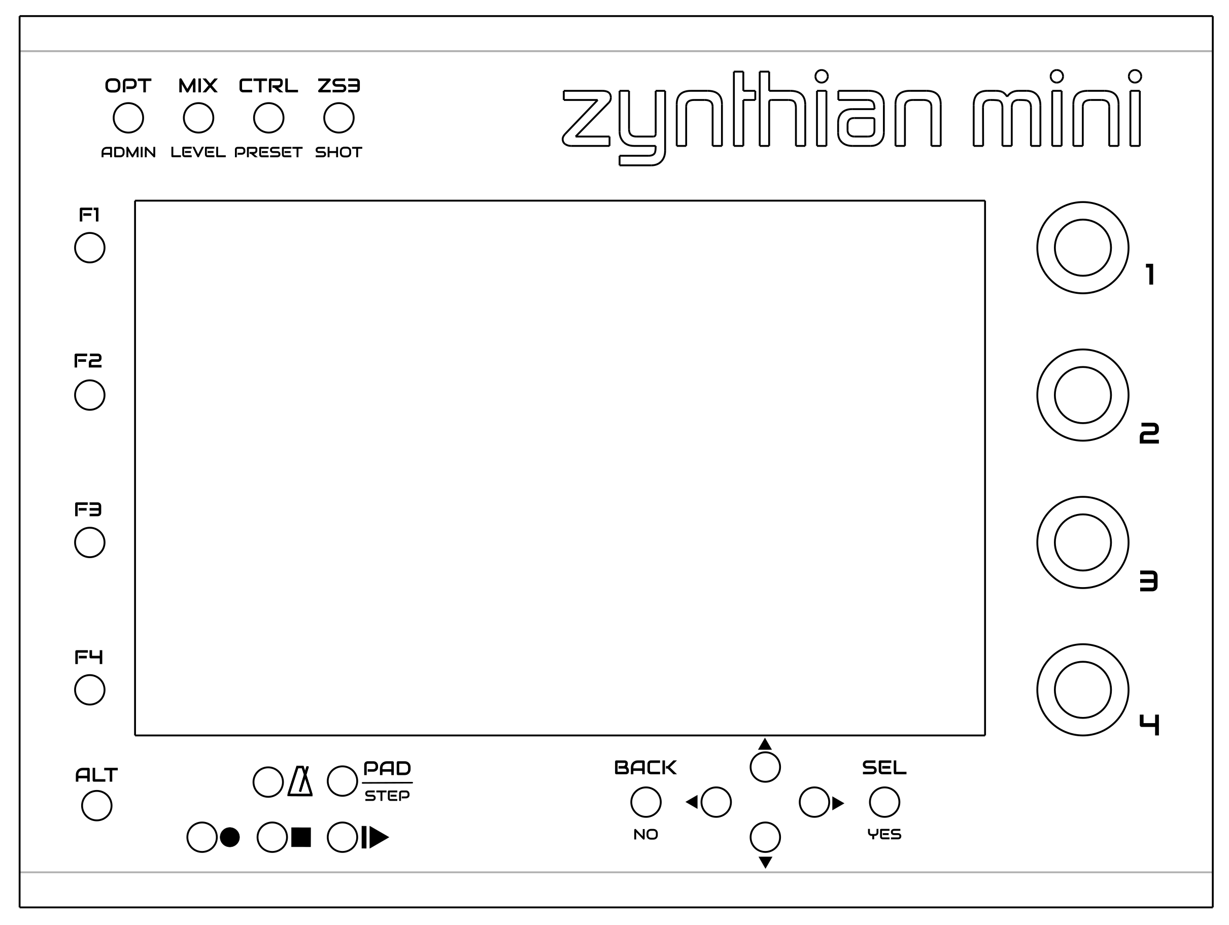
I need to document purpose of each zynthian mini button. Before I do that I would like to define their labels that are as close as possible to v5 button labels so that documentation is the same . While doing this I discovered that I will need to slightly re-arrange few buttons so that label fit nicely. Look at the current design and how messy would be the labels close to metronome button :
Stojos!
I love your Version of the zynthian, because it helps people like me, who cannot design pcbs etc… Already had a look into kicad, but are too afraid to break some thing.
I have everything to go already, most parts were mend for a
DIY Version of the V5 but I haven’t had a solution for the buttons…
Almost everything I want to integrated - like a hifiberry - is possible but:
Is it possible to have slightly bigger buttons? Or even ones which could carry a symbol?
I know these little push buttons sit on the pcb and therefor no wiring is necessary. What about these?
I wonder if these little knobs a ‘handy’ enough for a musicians key hammering? i.e. at the looper?
Or do rubber versions smaller than in V5 exist? Or maybe a least the record, stop and play buttons…
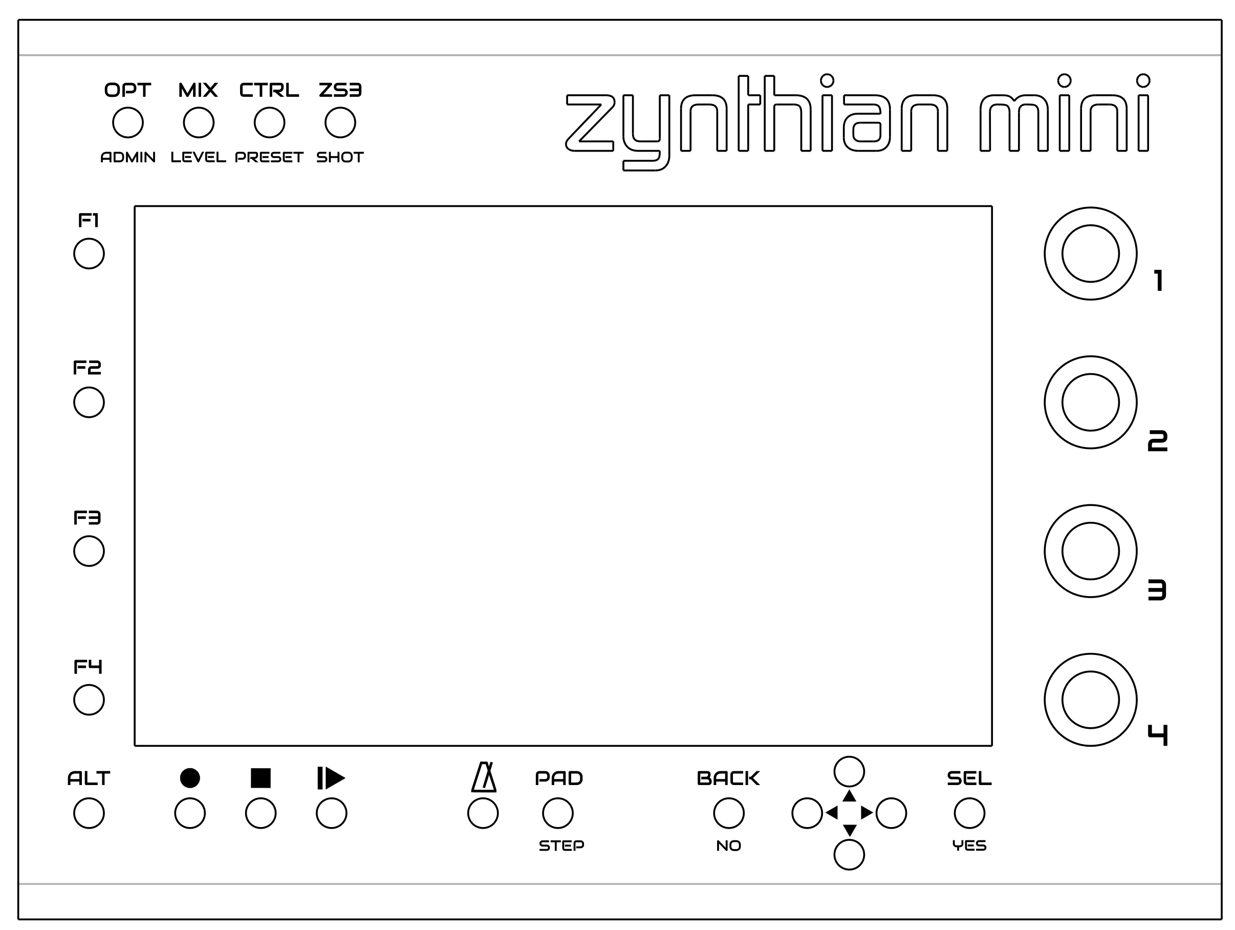
I like you new arrangement much better.
Again, thank you so much for you work!
Best from Berlin
@Fresh030 - apart from transport control buttons such as record, stop, play/pause and metronome button no other buttons have a purpose to trigger something at precise time. Even these buttons listed above are not primarily used for this.
If we want to make any button to really be used for playing or recording on time and maybe even with velocity sensitivity this would dramatically increase the cost.
My personal view is that playing should be done by midi controllers. They often come with pads.
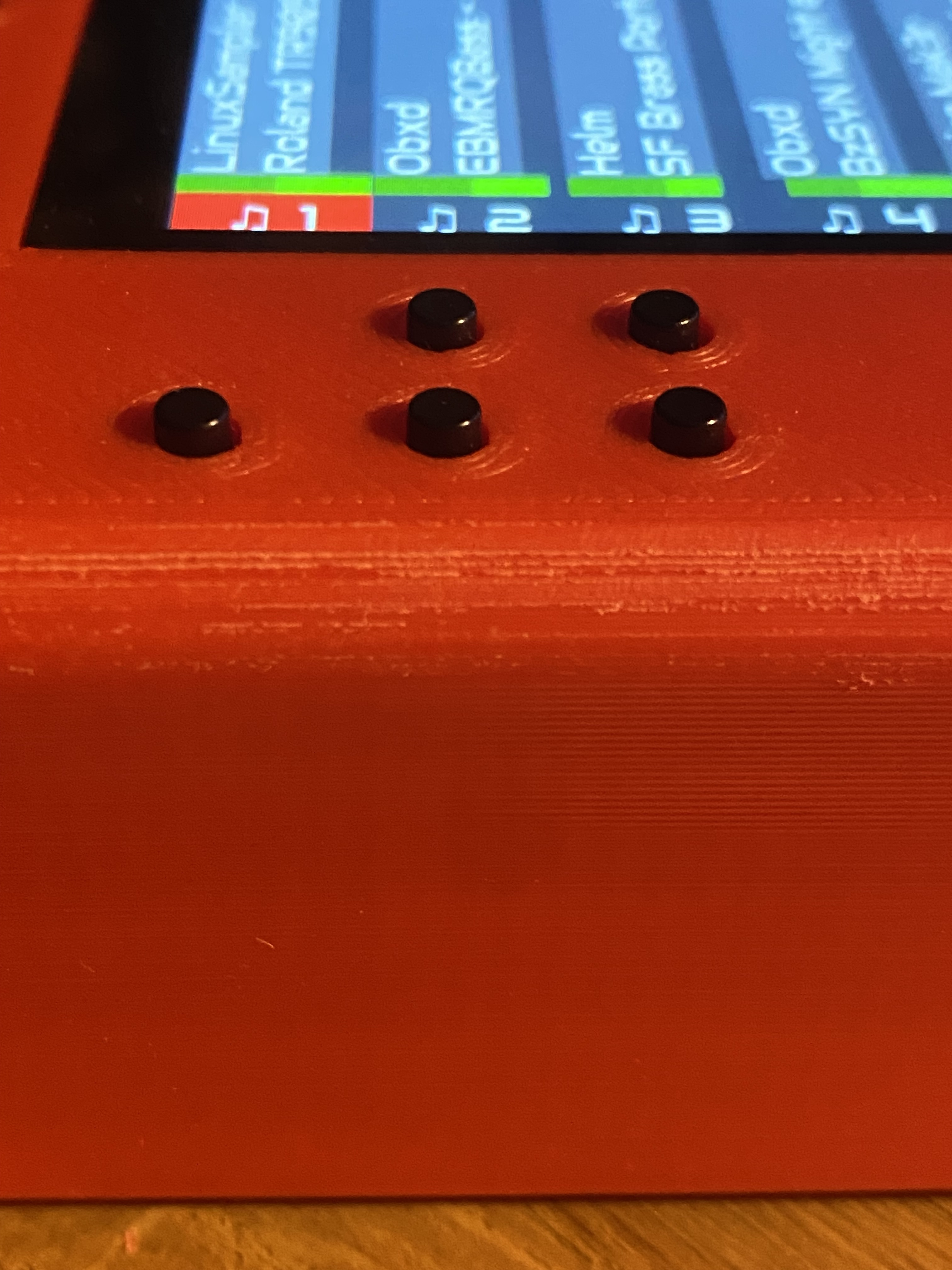
I use 13mm long buttons so that they just come above the screen top. Therefore whatever case you put zynthian where top of the screen is flat with the top of the case you will get button just sticking out 1mm that get them really easy to use. I don’t have any issues with them in case that I printed neither I think they are harder to use then what you linked in your post.
I am also designing a top facia for people that don’t have a way of 3d printing the case. This facia can be attached to pcb with hex posts and its top will be aligned to screen top. It will be possible to order it from same pcb manifacturer. They will also include appropriate labels that I am asking people here to give me some advice.
Finally, adding a led to the button is not easy or a cheap when you have 20 buttons. For example v5 uses a specific protocol for driving button leds in a matrix for which you need a specific hardware to read a protocol and ligh led inside the matrix accordingly. This means that raspberry is just sending instruction to this additional hardware what to do and it does not do it itself.
They really work very well even when they are close to each other like this. You can’t wrongly trigger them because they need to be properly pressed. The good thing about that is that you can touch them to fill them before pressing and not be afraid that the they will be triggered while doing that.
Well designed. i built two of this design. to anyone on the fence this is an easy build and very easy to set up with the webconf app. but before configuration do run the software update. i am running oram build and it is very stable. i am testing with various audio hats so its very well suited for that. big thanks to stojos for the PCB design and to the zynthian software guys who have done a great job with oram build (its very snappy now) and adding the mini V2. very pleased with the finished design. only change i made was to add sockets for the ic2 audio card and did add a fan running at 3.3v. printing a case as we speak