Would it be advantageous to add legends to the front panel silkscreen to label the connectors? It can be useful to see where connectors are and what they do without having to tilt the device (too much).
I tried that but I could not use existing v5 legends that @jofemodo kindly provided me in svg format. Too big and when reduced looked odd. It has to be something different. I think that svg file of existing mini’s top facia labels is on GitHub if somebody would like to design labels in Inkscape that are nice but still small enough. Once we have design in Inkscape it is easy to put on pcb.
Lovely!
Very nice-looking hardware solution ![]()
Hi! @stojos, thank you so much for this (and to the whole zynthian team). This is amazing! I just ordered all items in the BOM.
A couple comments from that list:
- Link 4 (Capacitors - Ceramic - Non-Polarized 100n and 10n) was unreachable for me. I ordered some other ones. Will 50V ones do? Voltage was not specified.
- I understand that the audio DAC could be replaced by a hat (I have a hifiberry around), and in that case this would be optional.
- Also the RCA and MIDI connectors should maybe be removed or marked as optional in the BOM - too late for me

Total was ~ 95$ if anyone is curious. I replaced some sellers with others offering the same item with free shipping. Now I’ll have to wait weeks if not months for delivery…
I guess that the pcb will take less time, so I’ll wait for the link to your latest version order from your supplier or jlcpcb or even the longer version if this is still planned.
I love the pcb fascia. The sides can be 3d printed in a contrasting colour, like this other interesting project (MAT 16x8 USB MIDI and audio interface).
2 Likes
100n need just to be small so that they can be easily soldered (there are 24 of them) inside existing small footprint - volatge is not important.
That is correct. Just be careful that you can not have both cards (on the PCB and in HUT) at the same time. They would use the same rpi GPIO pins and these can not be shared. If you want to swap the cards occasionally put PCB audio card on the female pin headers like this so that it can be removed when you use audio card in HUT.
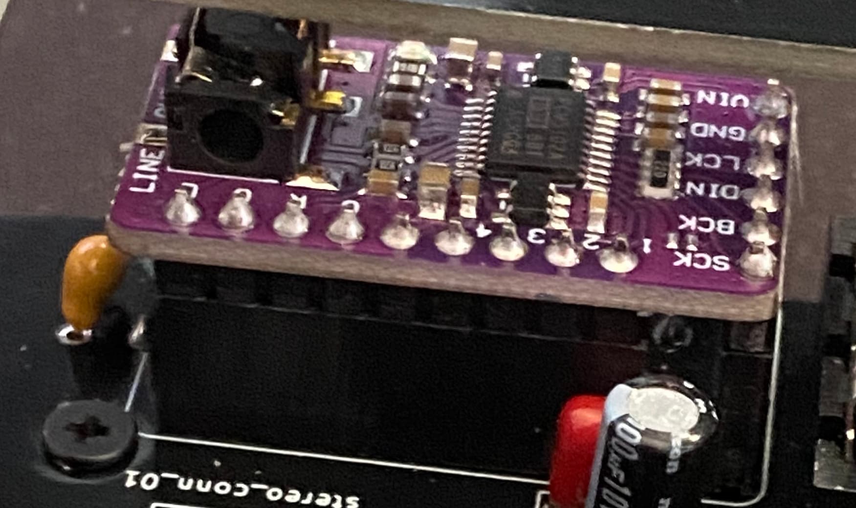
RCA is not any more in schematics. There is a 1/4" stereo connector that PCB audio card is wired too that also come with additional pin header connector to connect HUT card audio-out when PCB audio card is not used. MIDI connectors can also be omitted too if you have panel mounted connectors. PCB has pin headers for all three MIDI connectors where you can plug panel mounted one. Just be carefull that again you can not use both. If you solder PCB mounted MIDI connectors pins to connect to panel mounted MIDI connectors will not be available any more.
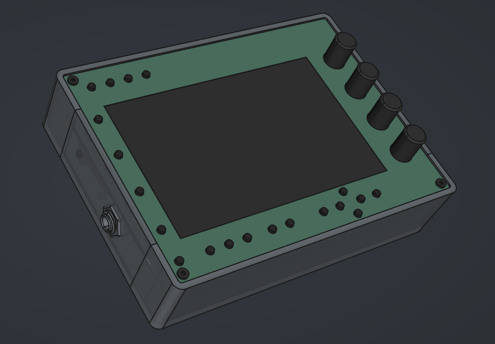
Yes, I am finishing design of 3d printed sides that can be simple attached. I am trying to design it without a need to use any screws so that they are just clicked into position. Here where I am at the moment:
5 Likes
Here is the latest report on Mini PCB and PCB facia that I have tested this weekend.
Main PCB is fully functional and no issue with it at all. It just takes few hours to solder everything together.
PCB facia works nicely but it can be further improved.
- push button holes can be with smaller radius. I used the same radius that I use for 3d printed case but holes on PCB facia are produced with much better precision so there is no need for such a big tolerance.
- KiCad PCB facia design have front and back swapped. This is because I simple copied main PCB design when making PCB facia so that dimensions are kept the same. This means that order number that is typically printed on the back by production companies now appears on the front. You can spot it on the top of the PCB facia.
- it would be good to have connector labels on the front as they are on V5. I will include connector labels into 3d printed enclosure design but it would be nicer to have them on the top facia and simplify printing process. Any volunteers to help me there?
I will work on these facia improvements but if you want to order PCB as it is here is the link to my pcbway orders. I am getting 10% of every order which is almost enough to buy me a coffee.
10 Likes
Super nice @stojos !! You did an excellent work with the MINI.
Aesthetical tiny details IMHO:
-
I would put the knob numbers just down the knobs
-
I would align the 4 top buttons with the display and the bottom buttons.
-
I would consider to move upside the zynpad/pattern button. I’m not sure about this. I understand your motivation to put it down, but i would give it a try.
-
I would reduce a little bit the logo area size and perhaps will look for a nicer composition of the 3 elements.
All the best!
1 Like
Thanks @jofemodo for, as always, honest and constructive feedback !
You are right, I did not spend enough time on adjusting logo size.
This is not possible with thru hole push buttons due to MIDI connectors that are in the same space. Maybe with smd push buttons it will be possible. However that would mean probably having smd components on both sides of PCB which increase the cost of their assembly in china. I am working on design with smd components so I will evaluate this further.
If I understood you well you ment moving pad/pattern button to be in the same group as top 4 buttons. I agree that it could be more logical but it will be make MINi layout more different to v5 layout. Still there is a problem with space that need to be resolved.
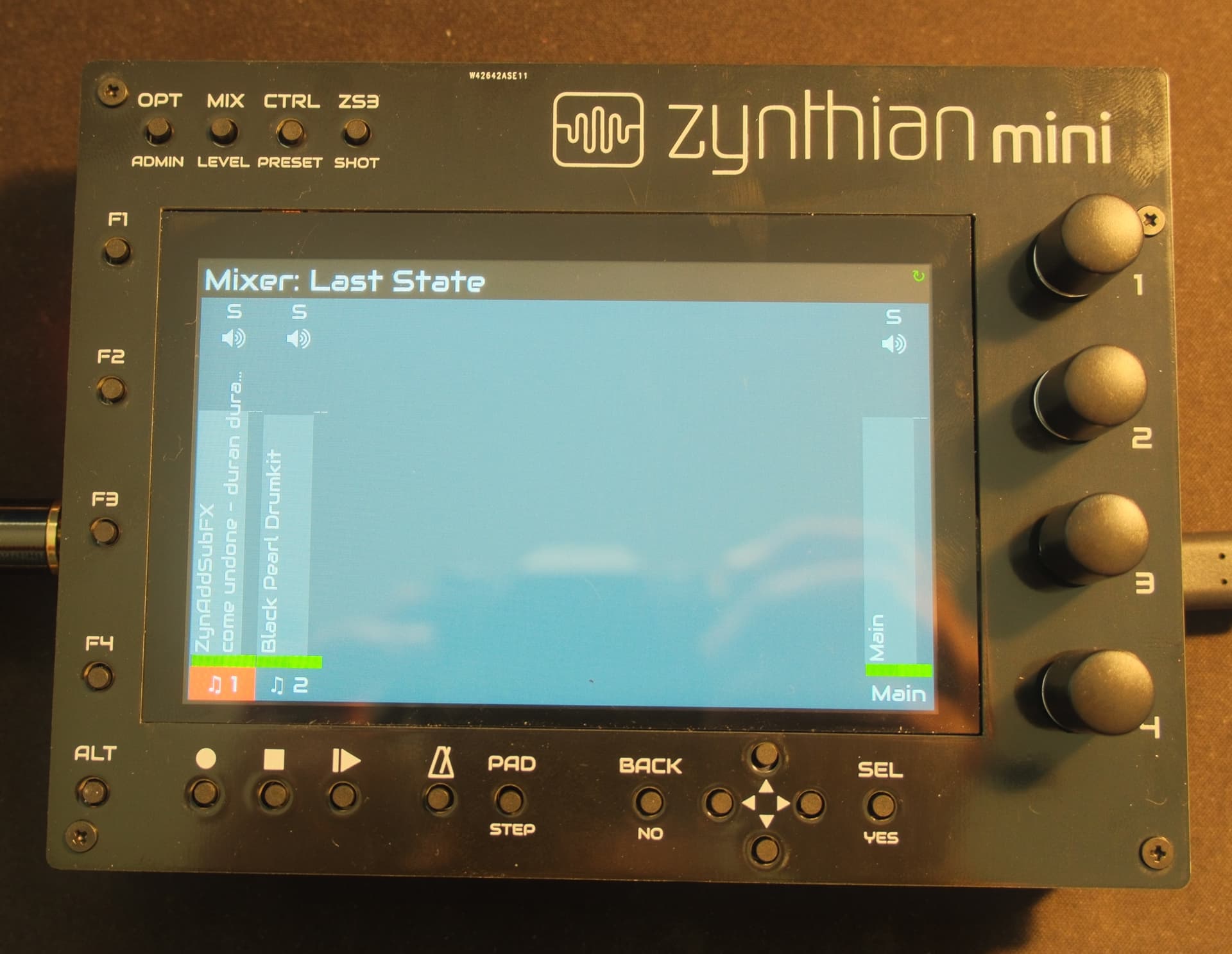
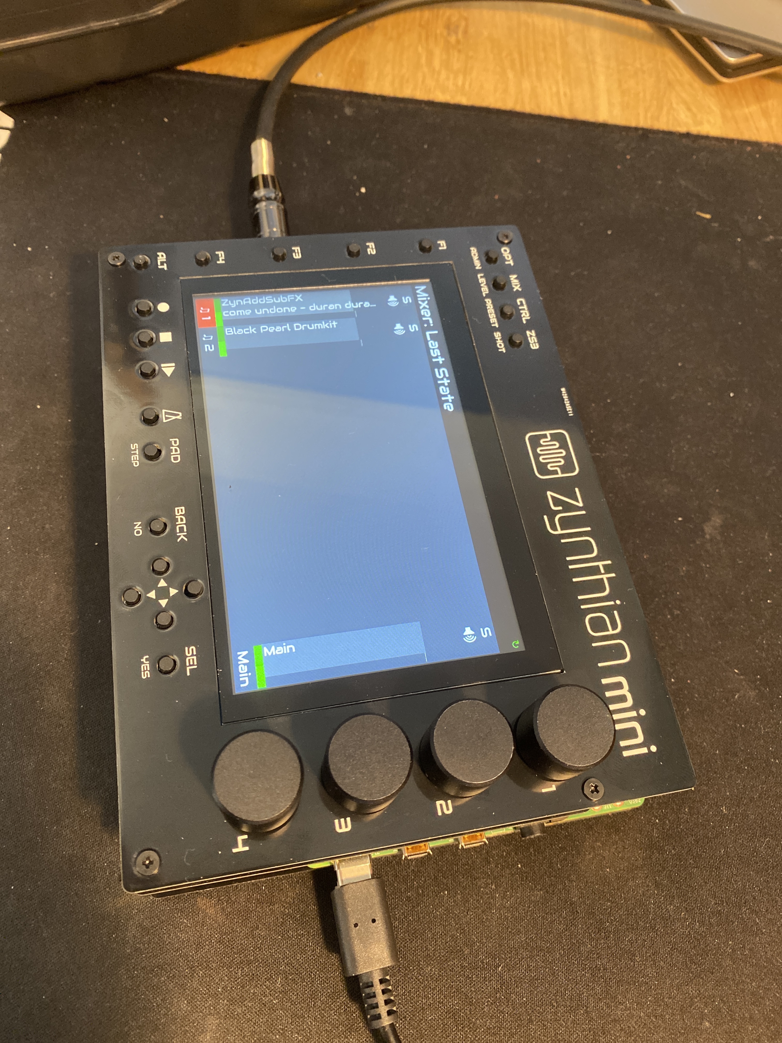
I tried to leave more space around knobs so that bigger knobs can also be used. It is hard to find knobs that are narrow and don’t have indicator. I could find only one that are narrow (only 12mm) and without indicator but they are not aluminium one ![]() - they are on the photo above. Here is the same setup with bigger knobs (16mm) that are easier to find that are still ok to use (not as nice)
- they are on the photo above. Here is the same setup with bigger knobs (16mm) that are easier to find that are still ok to use (not as nice)
Cheers!
2 Likes
I have used these knobs from aliexpress. They are small, without markers but are plastic:
I have also used these metal knurled knobs on D-shaft encoders even though they are not D-shaft knobs - the users haven’t noticed!
These look lovely but there is absolutely no detail - like they don’t exist!
I’ve ordered the main PCB for now. Are the design details (KiCAD) updated in the github as well?
The shipping costs were steeeeep, and since I’m not in a hurry (the components are slowly coming from Aliexpress), I selected one of the cheaper options, not available over a certain threshold. So I left out the fascia for now. I might check other materials. Thanks and enjoy your coffee ![]()
Yes, KiCAD design here zynthian-hw/MINI_V2 is the same as what is in shared order.
Yes, pcbway default shipping cost is expensive but is very fast. I also most of the time select the cheapest one whuch is not that slow - arrives in UK between 7-10 days.
PCBWAY will not accept order without copper layer simple because they would need to mill everything - so yes facia has copper on both sides - which is as you said good thing.
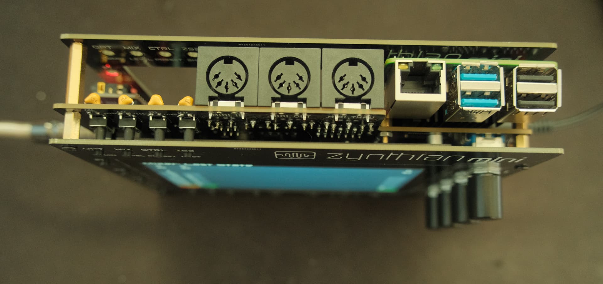
I can confirm that rpi 5 is working on MINI v2 out of box. I have just put latest Oram sd card taken from rpi 4 and inserted into rpi 5 and everything works, screen, encoders, buttons, audio out. I have not tested yet MIDIs.
It is even easier to put rpi5 into mini because the heatsink is now attached to its own posts instead of hut posts. Also fan is connected directly to board with very small connector so all is very neat. Fun is only switched on during boot, most of the time temp is low enough that fun is not on.
Do not forget to buy adapter cable for screen. New rip 5 dsi connector come with a different smaller connector. They are 1£ and shortest one that you can buy is 20cm which gives even easier way of connecting rpi 5 to mini because it is longer then one that comes with a screen.
i am waiting for hifuberry dac2 adc pro to arrive to test it inside mini - specifically audio in that @jofemodo is struggling to get working on rip 5.
4 Likes
Kudos @stojos, for having implemented this fantastic sister-project of Zynthian, which also happens to be fully Rpi5+Oram compatible ![]() .
.
I am probably asking something already available somewhere in this thread (sorry for this) but, could you maybe point me at a full PCB and components ordering + building instructions documentation?
I surmise that 3D-printing the enclosure I might be free to choose whatever ABS colour for Zynthian Mini I fancy more, right?
Thanks, and congrats on your achievement!
You can find this information here Building Zynthian MINI V2 - ZynthianWiki
Zynthian case is in FreeCAD format. Instruction above will tell you where freecad file is on zynthian-case GitHub. You will need to open it in freecad, select part (top, bottom, sfcard door) and export into stl. STLs on GitHub are old.
You can order PCB to be built. Link is few posts above.
1 Like
Yes, colour depend on your filament. I printed mine in red PLA, not yet printed in ABS. I am planning to print one in white PLA or maybe even translucent so that I can stick black labels printer on water slide decal.
Also have in mind that you can order pcb facia with already printed labels. Then you just need to print surrounding enclosure - I have printed one but not yet published design for it. I am not 100% happy with it.
1 Like
Thanx, all clear! ![]()
We discussed the idea of reducing the height of the PCB and front panel with a view to making it fit in a Eurorack enclosure. @stojos have you considered this any futher? I am building my rack mount zynthian and although it isn’t eurorack, it would benefit from a 3U form factor. (I may try to squeeze it into 2U… but I thought I would take a look here in case there is anything useful to borrow.)
Let’s scatch something first before adjusting the PCB. I am busy this weekend so I will create some drawing that we can discuss next eeek.