@riban - I always admired people that without any calculation where able to imagine in their heads exactly what is happening with current or voltage inside complex circuits. I experienced that first hand in late 80 while doing my computer science degree that did have a reasonable electrical engineering course.
Sadly I was not one of them because I did not have any training before uni and at uni you are immediately confronted with a theory and formulas without teaching you staff like this. They purposely avoided this because, as you said, it can be misleading but when you are designing circuits this really helps to not make rookie mistakes.
My degree was in the physics of electronics, i.e. the low-level stuff that makes all the magic happen. Hot electron theory, etc. I am glad I learned macro electronics as a hobby before that because much of the science I learned at university has long been forgotten and had little benefit in my career and hobbies whereas the analogies I learned when first learning about electronic cicuits remain useful over 40 years later. We should use whatever theories hold true in the context we are working. I don’t need to know that electrons flow the other way to be able to comprehend that a battery will power a light bulb. Niether do I need a deep understanding of Kirchoff but it is definitely useful with all but the simplest circuits. In England we have a saying, “Horses for courses” which means you use the appropriate thing for the appropriate use. Choose the theroy that works at the layer you are working. Newtonian physics is great for deciding how long it will take for a ball to drop but may be of limited use to decide how long an atom will decay.
Sorry - what a load of off-topic divel. All I should have said is, keep your capacitors close (and your enemies closer).
@riban totally agree with you. What you call “macro electronics” knowledge is even more important to know when you start designing analogue devices that include transistors that are much more complex to understand than resistor, capacitors or diodes.
Is there any good books to learn what you describe as “macro electronics” ?
I may be out of touch having learned lots then spent several decades forgetting. The best electronics book I bought was The Art Of Electronics by Harowitz & Hill. This was the bible for several generations of electronic engineers. I’m not sure how well it acts as a training device (although it should be good for this) as I bought my copy after I had learned a lot and tended to use it as a reference rather than a training aide
I would imagine there are lots of good online training courses now.
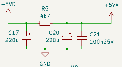
While we are talking about power supply filtering, I found this for filtering 5VD to 5VA,
Any opinion about this layout?
5VA is for feeding PCM1808 ADC. Its datasheet specify 11mA max current consumption for analog power.
Bonus question
From datasheet regarding DGND and AGND:
To maximize the dynamic performance of the PCM1808 device, there are no internal connections to the analog
and digital grounds. These grounds should have low impedance to avoid digital noise feedback into the analog
ground. They should be connected directly to each other under the PCM1808 device package to reduce potential
noise problems.
I choose to have one common ground called GND in my design. Bad idea ?
I know this is an endless discussion with people debating pro and cons in endless threads in DIYaudio or EEV Blog forum …
I have open the kicad project and I’m glad to see that all GPIOs are duplicated: good if one wants to use the 4 stereo out hat from Hifiberry.
If I can suggest an improvement: if possible move this connector so that the “right side” (where the audio connectors are) of the hat align to the right side of the board.
Did you open kicad project file from official zynthian repository: zynthian-hw/MINI_V2 ?
This is latest design. I am not maintaining any more my original GitHub repository apart from the fork of zynthian’s zynthian-hw but that fork is now fully synced with upstream.
In regards of connector I assume you are referring to HUT connector. I believe that it is there due to screen’s pcb that has some components very high and I was worried they would touch pins of the soldered HUT connectors. Or maybe one of the posts would be too close. Can you draw quickly on the Kicad pcb screenshot what you meant?
Hm, I think I know what you meant. I didn’t want to align hut with side where audio is because some people would like to use mini’s audio card slot and put some other non audio hardware in hut. If you put another audio HUT to improve mini’s audio, then these better audio huts have typically additional audio pins for their audio in/out and these should be connected to pcb additional audio pins so that card audio is routed to pcb audio connector when you don’t use mini’s audio card. I will maybe add one more audio connector so that there are at least 2 stereo connectors available for huts to connect to.
I want to order a set of pcb and the faceplate: please can you put on the repository a zip file containing the right files aligned with the last version to place an order to pcb service?
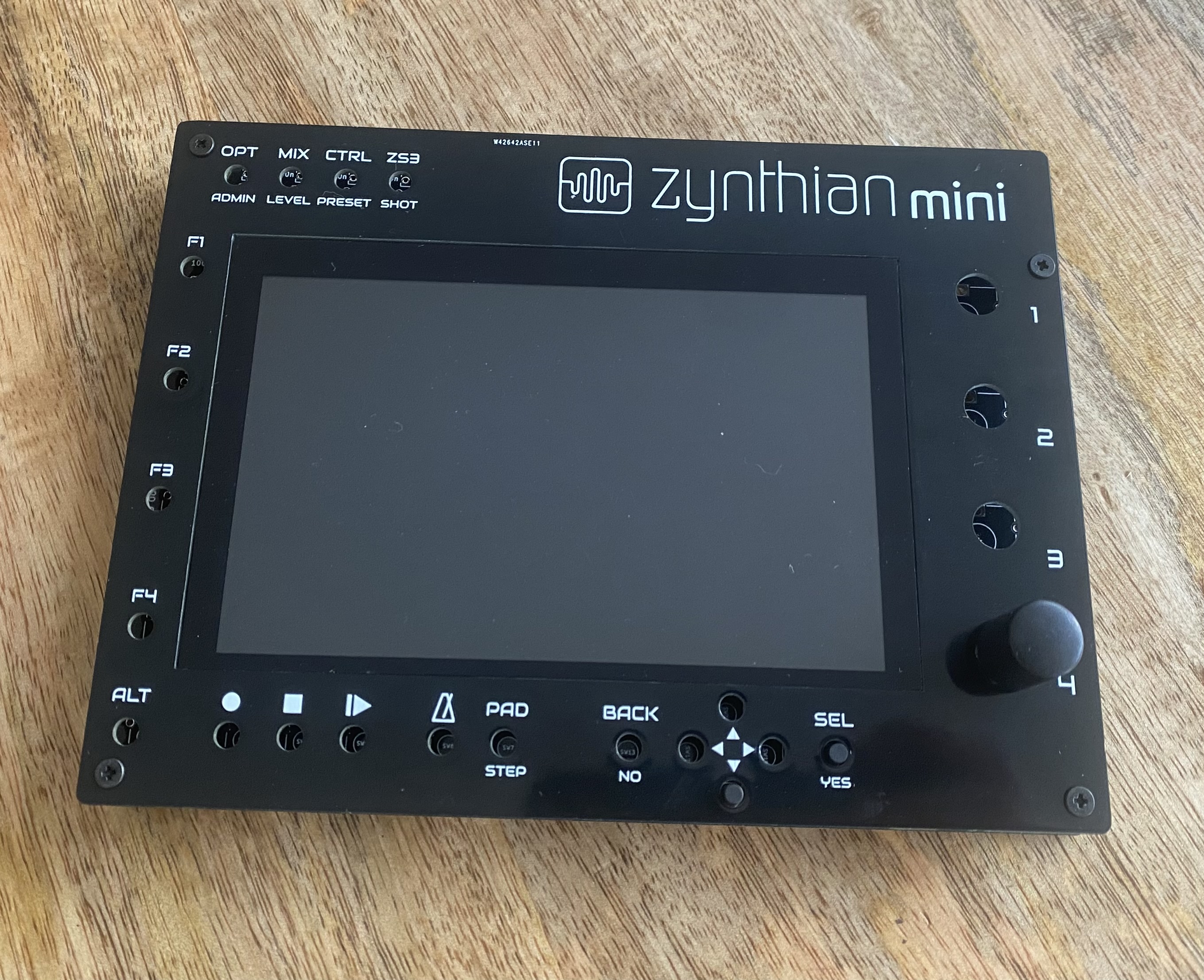
I want to know also the lenght of the buttons and the encoders to fit the faceplate (probably 13mm for the buttons and 20 mm for the encoders).
The front panel looks really cool - well done. Something else I should have mentioned during the last ZynthClub (when we were discussing PCB as front panels) is that you can specify the location of JLCPCB reference number (or pay a little extra to remove it completly). For front panels you can put it on the back which means it won’t be seen.
Well spotted. this is not produced by jlcpcb but they all do the same and put by default order number as silkscreen on the back of pcb. This was my mistake setting front to be back so order number appeared at the front.
I am worried that not all pcb manufacturers use the same rules when exporting Gerber files so I did not do that. As soon as I test this set of PCBs I will share the link of my pcbway order so that anyone can simple order the same.
@mesgia, you can also open the kicad project file and export the gerber files by yourself. In my experience, the standard gerber export generated by kicad works for most PCB manufacturers. If not, they will tell you how to generate. They are very used to kicad.
Everything is explained on zynthian wiki page Building Zynthian MINI V2. There is designated section with a list of components, their details and AliExpress link.
Another thing I remembered that we may not have mentioned before is that, when building front panels from PCBs I always flood both front and back with full coverage copper, i.e. not using any clever hole algorithm for heat disipation / distortion avoidance. Having copper on both sides increases the robustness and rigidity of the panel.
@stojos , thanks but the problem on the list of components is on the link of the buttons that point to the 5mm version and this no correct (for my opinion) if you have the faceplate. Same story for the encoders that link point to the 15mm but using the faceplate probably is better to have the plumm20 mm version.
Plase specify both values that are you using!