The documentation says:
PIN 12, 13, 15
The software did not find your switches. What you see is just the software defining the switches of the complete build. You use HW-version PROTOTYPE-4, which conflicts with the pins of the Waveshare.
You could try to use hw version “PROTOTYPE-KEES”, which has the right pin layout for the waveshare and the Hifiberry Dac+. Use the wiringmatrix as in the fifth post when hooking up the encoders and midi.
Afaik the three buttons on the display are used as mouse buttons for the touch screen and read via SPI and thus not usable for the Zyntian UI.
Edit: pins are indeed on the pins 12, 16 and 18, but I desoldered them 
Good luck!
Kees
yes, i found your layout in zynthian_gui.py
…don’t know how to change hw_version yet…but i will figure it out…
here it is:
zynthian-ui/zynthian_gui_config.py
I have sound now. Connected a USB midi and it works.
Kind of. There is random noise and when I press the first button, the synthi-sound stops.
I guess, that’s because the first button is on PIN12, which is used by HifiBerry as well?
So if I wire PIN12 (and the other 2 - 13, 15) to the PINS, the Zynthian Controller expects them, it should work?
This is PIN22 and 33?
Only 2 knobs have a press/switch event? Or where are the other two?
Hi @mheidt
the other two buttons are not directly connected to a GPIO pin - they are connected via the I2C I/O extender (MCP23008). If you have free GPIO pins you can use them but I think you have to make patches for the zyncoder-library to work with this layout.
Regards, Holger
I got my kit yesterday and tried to follow up. The new kit doesn’t have 2 dual controllers but 4 single ones.
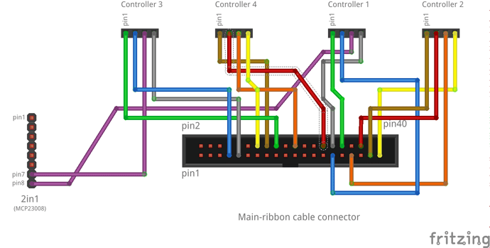
If I understand correctly, the pins 1-4 are B, A, Switch and Ground?
Kees’ controller 2, pin 2-4 is now controller 3 pin1 and controller 4 pin 2,3, which have to be moved.
Pins 1 are ground?
So
Enc3-RB pin 2 (A) moves to pin 18 of the PI
Enc4-RO pin 3 (B) moves to pin 30 of the PI
Enc4-RO pin 4 (Sw) moves to pin 22 of the PI
I see that A and B are swapped compared to my layout, so if your encoders turn the wrong way around, swap pins 2 and 3 on the encoder 
Cheers,
Kees
Thx for the layout. When I hold the controller so that I see the back, pins facing down, left is pin 1?
Hence 4 is ground? F.e. the yellow cable which is connected to 39 in the latest picture which Fernando changed 2 days ago.
According to the Wiki, you are right. I pulled the layout from there too, so there is some inconsitence in the wiki 
http://wiki.zynthian.org/index.php/Building_a_Zynthian_Box_using_an_official_Kit
Hi Guys!
You are right! I’ve fixed the inconsistences and now the schematic fits the color wiring sheme.
Regards!
I’d like to share my experience with the KEES wiring. I have the latest version running and changed the wiring via the webconf.
I had to set the waveshare32 manually, because it’s not in the selection list (yet).
I started with the wiring I found in the wiki(s) and had to change more than the 3 pins, that were mentioned here.
I swapped the physical location of “channel” and “back” and on the right, “LoadSave” and “Select”
On the left, the rotation direction was not correct, so that I had to swap two pairs as well.
This is how the waveshare32 works for me right now with the KEES wiring:
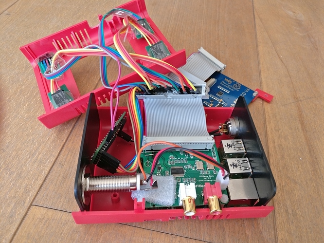
And most important. You need a female connector on your ribbon cable for the waveshare32.
It’s easier to change the wiring by software. You can do it from the webconf too ![]()
Anyway, could you detail your wiring layout, physical and logical? Perhaps you could send a modified version of this file:
I would like to add to the wiki an “alt wirings” section …
Thanks!
I’ve added more waveshare displays to the webconf tool. Touch calibration probably will not be OK, but display should be fine.
Note: I’ve used the “official” standard values from Waveshare. For WS3.2 rotation is 270 and you are using 90, so probably you have installed the display in inverted position. Easy to fix ![]()
Regards!
I added the following into my zynthian_webconf.py
[“PROTOTYPE-4-WS32”, {
‘ZYNTHIAN_WIRING_ENCODER_A’: “26,25,5,4”,
‘ZYNTHIAN_WIRING_ENCODER_B’: “21,27,7,31”,
‘ZYNTHIAN_WIRING_SWITCHES’: “107,23,106,6”
}],
I moved KEES after Prototype-2, because this seemed to be the original base.
And I changed the fritzing picture
Hi @mheidt!
Have you tried the official wiring with clean PROTOTYPE-4 layout?
It should work, and i’m thinking of removing some wiring layouts, not adding more … 
Regards!
yes, i did. White screen or ERROR screen. Can’t remember.
@jofemodo PROTOTYPE-4 does not work due to wiringdifferences between the PITFT and Waveshare, resulting in conflicts and failing software, that’s why I started this tread…
@mheidt So, the only difference between your and my lay-out is the order of the encoders. All the wiring is basicly the same…
OK! I missed some information. My brain is a little bit overloaded … jeje!! 
Regards!
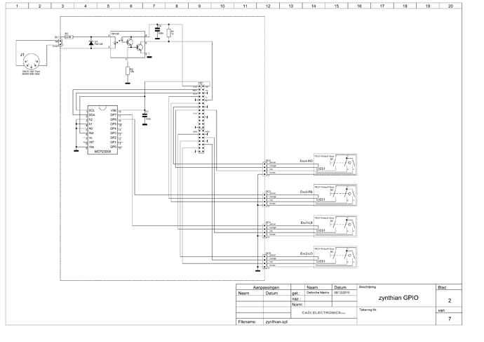
Can you share schematic Siring your build please
This is an old topic and a special wiring is not needed anymore, if you use the AllIn1 board (MCP23017).
If you don’t you should.
If you really can’t use a MCP23017, the wiring is written in the forum. Just search for it and please stop to beg for it. It should be the same as the Waveshare32
You need to do your homework first and read before you ask.
You get instant help, if you show us the reason for the red Error. Again. There is a wiki entry where you can find information how to access the zynthian and start it so that you see the log messages.


